



















Custom Titanium Anode Design: Engineering Fundamentals
Custom titanium anode design requires matching high-purity unalloyed titanium substrates (ASTM B265 Grade 1 or Grade 2) with multi-component Mixed Metal Oxide (MMO) catalytic coatings to minimize overpotential and resist chemical passivation. Precision dimensionally stable anodes (DSA) replace legacy graphite and lead-alloy electrodes by ensuring zero structural loss, reduced cell voltage, and exact dimensional stability over multi-year duty cycles.
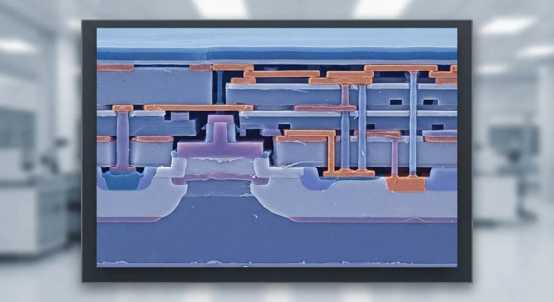
Industrial electrochemical efficiency depends on balancing electrical current flow, hydrodynamic flow fields, and electrocatalytic kinetics. Designing an optimized titanium anode involves calculating structural conductivity, selecting reaction-specific transition metal oxide matrices, and engineering substrate adhesion interfaces.
Dimensionally Stable Anode (DSA): An insoluble electrode consisting of an electrocatalytically active noble metal oxide coating thermally bonded to a valve-metal substrate (primarily titanium), maintaining invariant physical geometry and low overpotential during continuous electrolysis.
To establish an evaluation baseline for high-yield electrochemical systems, engineering teams must assess custom anodes using a three-dimensional framework:
Substrate & DFM Integrity: ASTM B265 Grade 1 chemistry with controlled mechanical roughness (Ra 4.0–5.5 µm) and ASME Section IX-qualified weld stress relief to eliminate coating delamination under current spikes.
Reaction Kinetics Matching: Tuning the catalyst formula for Chlorine Evolution Reactions (CER) versus Oxygen Evolution Reactions (OER) to suppress side reactions and lower cell energy consumption.
Sintering & Interfacial Kinetics: Deposition of nanoscale catalytic layers through iterated thermal cycles (typically 18 to 24 passes) to establish a low-stress, crack-resistant oxide crystal lattice.
Electrochemical Reaction Tailoring: CER vs. OER Catalytic Systems
Catalytic coating selection governs operational cell voltage and electrochemical selectivity. Deploying an incorrect oxide formulation causes accelerated catalyst dissolution, high parasitic overpotentials, and premature passivation of the titanium base metal.
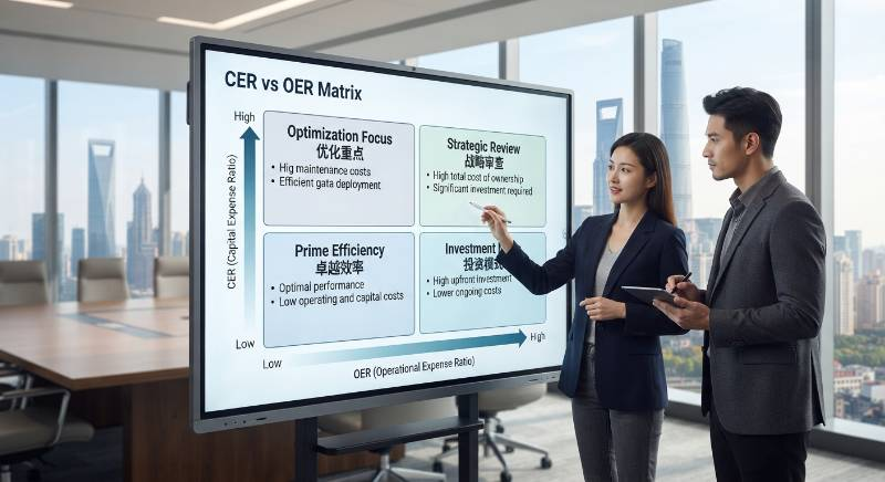
Chlorine Evolution Reaction (CER) Systems
In chlor-alkali electrolysis, sodium hypochlorite generation, and seawater electrochlorination, the anode must drive the selective oxidation of chloride ions:
2Cl- → Cl2 + 2e- (E° = +1.36 V vs. SHE)
The standard catalyst configuration consists of a ternary solid solution: RuO2-IrO2-TiO2. Ruthenium oxide provides high electrocatalytic activity with low chlorine overpotential (<40 mV at 3,000 A/m2), while IrO2 and TiO2 stabilize the crystal lattice against active chlorine attack.
Oxygen Evolution Reaction (OER) Systems
In acidic environments such as copper foil manufacturing, sulfuric acid electrowinning, and impressed current cathodic protection (ICCP), oxygen evolution dominates:
2H2O → O2 + 4H+ + 4e- (E° = +1.23 V vs. SHE)
RuO2 dissolves rapidly in low-pH oxygen-generating electrolytes due to oxidation into volatile RuO4. For OER duty, an IrO2-Ta2O5 catalytic matrix is required. Tantalum oxide forms a passivating, acid-insoluble barrier phase that protects the titanium substrate from localized corrosion and acid penetration, extending service life in solutions with pH < 1.
Substrate Metallurgy & DFM: Preventing Flaking and Edge Degradation
The mechanical bond between the catalytic oxide and the metal core dictates the ultimate physical life of the anode. Substrate design for manufacturability (DFM) must resolve interfacial shear stresses caused by mismatched thermal expansion coefficients between metallic titanium (α ≈ 8.6 × 10⁻⁶ /K) and mixed metal oxides (α ≈ 5.0–7.0 × 10⁻⁶ /K).
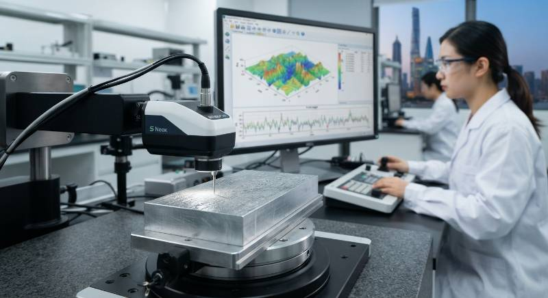
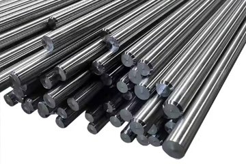
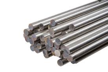
Using custom titanium manufacturing capabilities, high-current anodes are constructed using pure ASTM B265 Grade 1 titanium. Grade 1 provides low yield strength (<240 MPa) and high elongation (>24%), which minimizes residual internal stresses during stamping, expanding, and welding.
Engineering Insight: Edge-Effect Mitigation
Laser cutting and mechanical punching introduce localized micro-cracks and cold-worked heat-affected zones (HAZ). If coated directly, current concentrates at these sharp corners (radius < 0.2 mm), driving current densities 300% to 500% above the nominal rating. This causes premature micro-sparking and localized coating delamination. All edges must be radiused to R ≥ 0.5 mm via mechanical edge-breaking followed by chemical etching.
Substrate preparation requires four validated processing phases:
Alkaline Degreasing: Hot ultrasonic immersion (65–80 °C, 10% NaOH) to strip hydrocarbons and machining oils.
Abrasive Grit Blasting: Coarse corundum (Al2O3, 20–36 mesh) blasting under 0.4–0.6 MPa air pressure to generate an anchor profile of Ra 4.0–5.5 µm (Rz 25–40 µm).
Acid Etching: Boiling in 20%–22% hydrochloric acid (HCl) at 98–104 °C for 40 to 90 minutes, establishing a high-surface-area micro-pitted titanium hydride (TiHx) morphology.
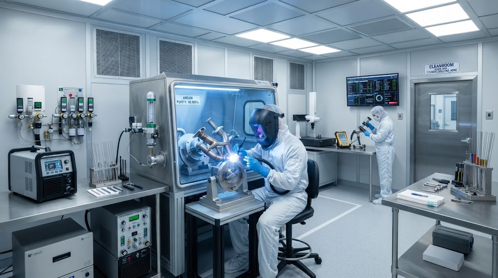
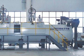
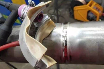
Vacuum Annealing: High-stress welded structures undergo vacuum stress relief at 540 °C ± 15 °C to prevent distortion during subsequent thermal coating cycles.
The Dual-Stage DFM & Thermal Sintering Protocol
To eliminate interstitial boundary voids and ensure uniform noble metal loading, production follows a rigorous six-stage thermal decomposition protocol.
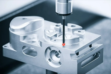
Phase 1 — High-Precision Substrate Profiling: Deep etching and automated coordinate measurement to confirm surface roughness and structural tolerances.
Phase 2 — Barrier Layer Application: Thermal deposition of an ultra-thin (0.2–0.5 µm) TiO2-Ta2O5 or TiH2 intermediate layer to prevent oxygen diffusion into the titanium matrix.
Phase 3 — Nanoscale Precursor Micro-Coating: Precise pneumatic or automated liquid brush coating using alcoholic solutions of RuCl3, H2IrCl6, and TaCl5.
Phase 4 — Low-Temperature Solvent Flash-Off: Controlled drying at 110–140 °C for 10–15 minutes to evaporate organic carriers without causing surface skinning or boiling blisters.
Phase 5 — High-Temperature Thermal Decomposition: Oxidation in an oxygen-rich atmosphere at 450–520 °C for 15–20 minutes, converting metal salts into an oxide solid solution.
Phase 6 — Multi-Pass Accumulation & Final Annealing: Repetition of phases 3 through 5 for 18 to 24 cycles to achieve target noble metal loadings (10 to 40 g/m2), concluded by a final 60-minute stress-equalizing post-bake at 500 °C.
Structural Geometry & Current Delivery: Mesh, Tubular, and Ti-Cu Clad Busbars
Electrochemical efficiency depends on uniform current distribution and rapid gas disengagement. Structural anode geometry directly influences bubble fraction resistance, electrolyte replenishment rates, and overall cell potential.

Expanded Mesh vs. Slotted Sheet Dynamics
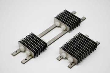
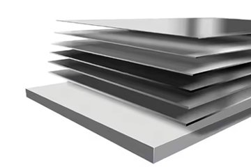
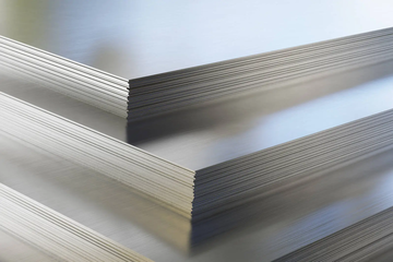
Expanded titanium mesh is the standard geometry for high-rate gas-evolution applications. Diamond aperture patterns (e.g., LWD 12.5 mm × SWD 4.5 mm) generate micro-vortices in the rising gas plume (Cl2 or O2), which continuously draws fresh electrolyte to the active catalytic interface and lowers the cell ohmic resistance drop (IR drop) by 80–150 mV compared to solid plate configurations.
High-Current Busbar Integration (Ti-Clad Copper)
Unalloyed titanium has high electrical resistivity (approx. 0.42 µΩ·m at 20 °C), compared to Oxygen-Free High Thermal Conductivity (OFHC) Copper (approx. 0.017 µΩ·m). Passing large currents through pure titanium structures introduces substantial resistive heating and non-uniform potential distributions.
Ploss = I2 × R
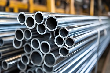
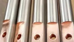
For currents exceeding 500 A, explosion-bonded or metallurgical diffusion-bonded Titanium-Clad Copper (Ti-Cu) busbars are necessary. A titanium sheath (typically 1.0–2.0 mm thick) protects the core copper rod from acidic electrolyte corrosion, while the high-conductivity copper core delivers uniform current across long-span anodes (≥2.5 m) with minimal potential drop (ΔV < 20 mV across the structural span).
Extreme Operating Scenarios: Low-pH, High-Current & Fluoride Media
Standard mixed metal oxide formulations degrade rapidly when subjected to severe mechanical, chemical, or electrical stress.
Ultra-High Current Density Foil Manufacturing (>10,000 A/m2): In continuous high-speed copper and lithium battery foil electrodeposition, high currents trigger aggressive oxygen bubble erosion and localized thermal spikes. Custom anodes require dense, nano-crystalline IrO2-Ta2O5 coatings with dopants like Ru or Pt, combined with heavy-gauge Ti-Cu core structures to manage thermal profiles and prevent grain boundary stripping.
Trace Fluoride-Bearing Wastewater: Fluoride ions (F-) attack the underlying passivating titanium oxide film, forming soluble TiF62- complexes that undermine and strip catalytic coatings within weeks. In electrolytes containing 5 to 50 ppm F-, we incorporate an intermediate platinum or conductive niobium interphase barrier beneath a high-density Ir-Ta-ZrO2 outer matrix to protect the base metal.
Reversible Flow & Polarity Reversal Conditions: In electrochlorination systems that utilize periodic current reversal for descaling, MMO coatings face extreme stress during cathodic cycles, which leads to hydride embrittlement. Substrates must undergo deep vacuum annealing, paired with specialized IrO2-RuO2 formulations engineered to tolerate cathodic polarization.
Quality Benchmarks & Verification: NACE TM0108, ASTM G210, and XRF Assays
Material traceability and non-destructive quality assurance are essential to verify that custom titanium anodes meet specified service lifetimes.

Quality verification for industrial lots involves four standardized protocols:
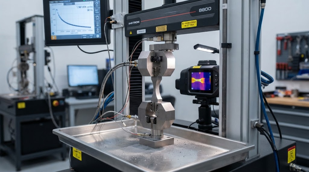
Accelerated Life Testing (ALT): Performed in accordance with NACE TM0108 and ASTM international test methods. Operating in 1.0 M H2SO4 at extreme current densities (10,000 to 20,000 A/m2) at 40–50 °C, cell potential is monitored until a 5.0 V deactivation threshold is reached, verifying underlying coating adhesion and catalytic life.
X-Ray Fluorescence (XRF) Spectrometry: Non-destructive assaying across the active face to map elemental ratios (e.g., Ir:Ta weight %) and confirm noble metal loadings (precision to ±0.2 g/m2).
Thermal Shock Integrity Test: Test coupons are heated to 450 °C in a muffle furnace for 60 minutes and immediately quenched in 20 °C water. Coatings must show zero microscopic micro-cracking, flaking, or delamination under 100× optical magnification.
Complete Documentation: Every production batch is certified with an EN 10204 3.1 Material Test Certificate (MTC) detailing substrate chemistry, mechanical tensile limits, and noble metal application logs.
Comparative Technical Specs: Coating Formulations and Substrate Types
The matrix below outlines standard engineering parameters for primary industrial coating systems and substrate configurations.
| System Type | Active Catalyst Composition | Primary Reaction | Max Current Density | Operating pH Range | Typical Service Lifespan |
|---|---|---|---|---|---|
| Ru-Ir MMO | RuO2-IrO2-TiO2 | CER (Chlorine) | ≤ 4,000 A/m2 | pH 2 – 12 | 4 to 8 Years |
| Ir-Ta MMO | IrO2-Ta2O5 | OER (Oxygen) | ≤ 15,000 A/m2 | pH 0 – 10 | 3 to 10 Years |
| Platinum-Plated | Pt (99.99% pure metal) | Mixed CER / OER | ≤ 7,500 A/m2 | pH 0 – 14 | 2 to 5 Years |
| Lead Dioxide | β-PbO2 (on Ti substrate) | OER (High Potential) | ≤ 5,000 A/m2 | pH 0 – 4 | 1 to 3 Years |
Frequently Asked Questions on Custom Titanium Anode Engineering
Can depleted titanium anode substrates be stripped and recoated?
Yes. Because the titanium base metal remains structurally dimensionally stable throughout its service cycle, depleted anodes can be mechanically and chemically stripped using molten salts or specialized acids. After surface re-profiling and grit blasting to restore the Ra 4.0–5.5 µm anchor pattern, fresh MMO coatings are reapplied at 40% to 60% of the cost of a completely new anode assembly.
When should I specify Ru-Ir versus Ir-Ta MMO coatings?
Specify Ru-Ir coatings when the primary reaction is Chlorine Evolution (CER) in chloride-rich, neutral-to-alkaline electrolytes (e.g., brine electrolysis, ballast water treatment, swimming pool chlorination). Choose Ir-Ta coatings for Oxygen Evolution (OER) in low-pH, sulfate-rich environments (e.g., electrogalvanizing, copper foil production, acid wastewater oxidation), as Ir-Ta resists rapid acid dissolution and passivation.
Why choose Titanium-Clad Copper over solid titanium busbars?
Solid titanium has high electrical resistivity (0.42 µΩ·m), leading to significant voltage drops, power losses, and heat generation at currents above 500 A. Titanium-Clad Copper busbars combine the superior electrical conductivity of OFHC Copper (0.017 µΩ·m) with the corrosion resistance of a titanium outer barrier. This setup cuts distribution power losses by 20% to 35% and maintains uniform current across large surface areas.
How is noble metal loading (g/m2) verified during production?
Loading integrity is verified through a three-stage testing process: (1) Gravimetric differential weighing before and after the 18–24 thermal decomposition cycles; (2) High-resolution non-destructive X-Ray Fluorescence (XRF) spectrometry across multiple surface coordinates; and (3) Destructive coupon validation using ICP-OES spectroscopy following chemical dissolution.
3-Step Engineering & Rapid Anode Prototyping Pathway
To eliminate design errors and streamline lead times, custom titanium anode projects follow a structured three-step technical deployment process:
Step 1 — Technical File & Operating Condition Submission: Provide 2D/3D fabrication drawings (.step, .dwg, or .pdf) along with key operating parameters: electrolyte chemistry, operational current density (A/m2), bath temperature, design service life, and pH levels.
Step 2 — DFM Review & Electrochemical Simulation: Engineering teams review the design to optimize gas disengagement geometry, calculate busbar IR drops, determine the appropriate coating formulation (Ru-Ir, Ir-Ta, or Pt), and establish target noble metal loadings (g/m2).
Step 3 — Prototyping & Scaled Production: Once the technical parameters and quotation are approved, pilot samples or full production batches are manufactured under ISO 9001 quality controls, backed by EN 10204 3.1 Material Test Certificates and XRF loading reports.
Request an Electrochemical Engineering Consultation
Speak directly with a titanium fabrication specialist to review your operating parameters, CAD drawings, and anode coating specifications.
request an electrochemical engineering consultation