






















Atmospheric Shielding Fundamentals & Titanium Reactivity
Titanium welding requires absolute atmospheric isolation because titanium becomes highly reactive with oxygen, nitrogen, carbon, and hydrogen at temperatures exceeding 427°C (800°F). While Gas Tungsten Arc Welding (GTAW/TIG) employs a single laminar gas column to protect the weld puddle, Plasma Arc Welding (PAW) utilizes a dual-gas delivery system to separate arc constriction from the outer protective envelope. Selecting between TIG and PAW determines the torch nozzle geometry, trailing shield volume, and root purge venting needed to prevent catastrophic interstitial embrittlement.
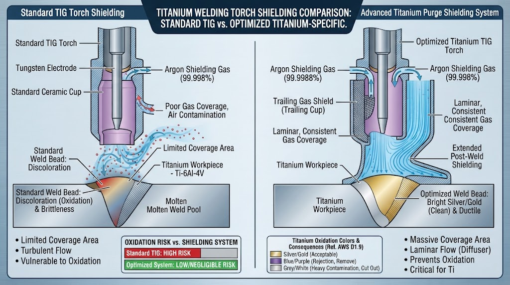
When exposed to air at elevated temperatures, titanium functions as an active chemical getter. Interstitial dissolution of oxygen and nitrogen into the hexagonal close-packed (HCP) alpha matrix causes severe lattice distortion. This process leads to the formation of a brittle surface condition known as the "alpha-case" layer.
Alpha-Case: An oxygen-enriched, brittle surface zone formed on titanium alloys during elevated-temperature atmospheric exposure, exhibiting dramatically increased microhardness, reduced fatigue resistance, and severe vulnerability to micro-cracking.
According to AWS D1.9/D1.9M (Structural Welding Code - Titanium) and ASME Section IX specifications, oxygen pickup exceeding 1,500 ppm above base metal levels degrades fracture toughness by more than 40%. In our manufacturing experience at China Titanium Factory, maintaining interstitial integrity begins with strict gas purity and verified environmental controls.
Total gas protection requires three distinct, synchronized shielding zones during any thermal cycle: primary torch shielding over the liquid weld pool, trailing shielding over cooling solid metal (from solidification down to below 400°C), and root/backing shielding protecting the backside penetration.
Shielding Gas Selection: Pure Argon vs. Helium Blends
Shielding gas purity is the baseline parameter for defect-free titanium fabrication. Standard industrial argon (99.99% / Grade 4.0) contains residual moisture and oxygen levels that can compromise critical weldments. For industrial, aerospace, and marine fabrications, Grade 5.0 Ultra-High Purity (UHP) Argon (99.999% purity) is required.
| Gas Type | Purity Level | Maximum Dew Point | Thermal Conductivity | Primary Application |
|---|---|---|---|---|
| 100% UHP Argon | ≥ 99.999% | -65°C (-85°F) | Low (0.0177 W/m·K) | Standard GTAW, PAW Shielding & Backing |
| 75% Ar / 25% He | ≥ 99.995% | -60°C (-76°F) | Moderate | Thick Titanium Plates and Heavy Sheet (>6mm GTAW) |
| 50% Ar / 50% He | ≥ 99.995% | -60°C (-76°F) | High (0.075 W/m·K) | High-amperage mechanization, deep penetration |
Pure Argon exhibits a low ionization potential (15.76 eV), providing reliable high-frequency arc starting, a stable arc column, and minimal surface turbulence. However, for heavy-wall components, pure argon can result in narrow penetration profiles.
Adding high-purity Helium increases the arc voltage and thermal conductivity across the arc column, generating a broader, deeper penetration profile. Despite this benefit, helium's low density (one-tenth that of argon) causes it to disperse rapidly upward. When using helium blends, operators must increase flow rates by 25% to 40% to maintain effective surface blanket coverage.
TIG (GTAW) Shielding Architecture: Torches, Gas Lenses, and Flow Rates
Gas Tungsten Arc Welding delivers a single, cohesive column of protective gas directly through the torch cup. Maintaining laminar, non-turbulent flow is critical to prevent drawing ambient air into the hot zone.
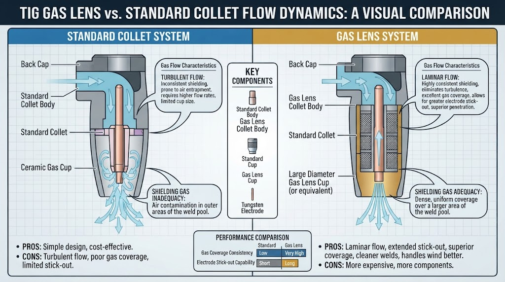
Standard collet bodies create erratic, turbulent gas exiting the ceramic cup, aspirating room air at the periphery. TIG welding of titanium requires an engineered gas lens assembly featuring fine, multi-layer sintered stainless steel mesh screens (200-mesh or finer).
Gas Lens Sizing: Standardize on large-diameter cups (No. 10 to No. 19, inside diameter 16 mm to 28 mm) to provide a wide protective footprint.
Flow Rate Optimization: Deliver 15 to 25 L/min (32 to 53 CFH) of UHP Argon to the primary torch. Excessive flow (>28 L/min) creates venture-induced turbulence, drawing oxygen directly into the molten pool.
Electrode Selection & Geometry: Use 1.5% to 2.0% Lanthanated tungsten (EWLa-1.5/2.0) or Cerium-tungsten (EWCe-2) prepared with longitudinal grinding marks and a 30° to 45° included angle with a truncated flat tip.
Torch Angle: Maintain a 90° perpendicular torch angle relative to the plate. Torch tilt angles exceeding 15° draw air into the trailing edge of the gas shield.
Plasma Arc Welding (PAW) Shielding Dynamics: Dual-Gas Architecture
Plasma Arc Welding differs from GTAW by passing an internal arc through a constricted copper orifice nozzle. This mechanical constriction splits gas handling into two independent delivery channels: Orifice (Plasma) Gas and Outer Shielding Gas.
The inner orifice gas forms the high-velocity plasma jet, while the concentric outer cup delivers low-velocity shielding gas to protect the surrounding base metal and molten pool edges.
| Plate Thickness (mm) | Orifice Gas Flow (L/min) | Outer Shielding Gas (L/min) | Welding Current (A) | Travel Speed (mm/min) |
|---|---|---|---|---|
| 3.0 mm (Melt-in mode) | 1.0 – 1.8 | 12.0 – 15.0 | 90 – 130 | 250 – 350 |
| 6.0 mm (Keyhole mode) | 2.2 – 3.2 | 15.0 – 18.0 | 160 – 210 | 320 – 420 |
| 9.5 mm (Keyhole mode) | 3.5 – 4.8 | 18.0 – 22.0 | 220 – 280 | 280 – 360 |
| 12.7 mm (Keyhole mode) | 4.5 – 6.0 | 20.0 – 25.0 | 270 – 340 | 200 – 260 |
Precision balance between these two flows is critical. If the inner orifice flow is set too high for a given material thickness, the plasma jet cuts through the plate without allowing the molten pool to coalesce behind the keyhole. Conversely, low outer shield flow fails to counter the high-velocity column's aspiration forces, pulling ambient air into the joint interface.
Keyhole PAW Backside Purge Dynamics: Preventing Root Underbead Blowout
In Keyhole PAW, the high-energy plasma jet penetrates completely through the plate thickness, generating an open keyhole cavity. The high-velocity plasma gas exits through the root of the joint alongside the molten underbead.
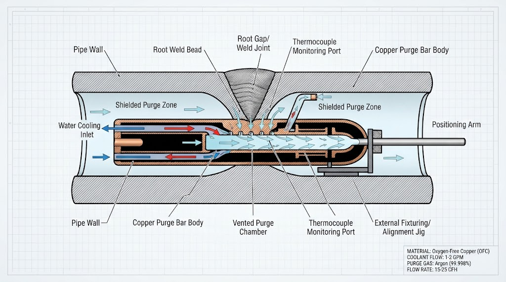
Standard enclosed backing channels used in manual TIG will fail under Keyhole PAW conditions. Confining high-momentum effluent gas inside a sealed backing bar creates local backpressure spikes. These pressure surges disrupt the molten bridge, causing severe root underbead blowout, cavity collapse, and heavy backside oxidation.
To safely manage keyhole dynamics, use an engineered vented root purge bar assembly with three functional design elements:
Dual-Chamber Geometry: Separate the incoming UHP purge delivery chamber from the plasma effluent exhaust line using a multi-porous sintered bronze or stainless steel diffuser bar.
Directional Vent Ports: Position calibrated exhaust ports (3.0 mm to 4.5 mm diameter) angled 45° away from the travel direction at regular 50 mm intervals. This maintains a slight positive pressure (0.5 to 1.5 mbar) while venting high-velocity gas.
Groove Relief Dimensions: Mill the primary root clearance channel to a minimum depth of 8.0 mm and width of 12.0 mm to prevent the exiting plasma stream from rebounding into the molten underbead.
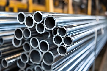
For fabrication of heavy-wall Titanium Pipes and Seamless Tubes, continuous internal oxygen sensors must verify levels below 10 ppm before initiating the pilot arc.
Trailing Shield Engineering: Manual TIG Speeds vs. High-Velocity PAW
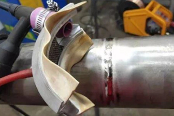
Because the primary torch nozzle only shields the active molten puddle, a secondary trailing shield (trailing shoe) is necessary to protect the hot solidified bead and heat-affected zone (HAZ) until the metal cools below 400°C (752°F).
Calculating the required active trailing shield length depends on the weld travel speed and the material's cooling rate:
Trailing Shield Minimum Length Formula:
Lts = vw × tc
Where:
Lts = Minimum active trailing shield diffuser length (mm)
vw = Welding travel speed (mm/s)
tc = Cooling duration from solidus temperature down to 400°C (seconds)
In manual GTAW, travel speeds typically range from 1.5 to 3.0 mm/s (90 to 180 mm/min), requiring compact trailing shoes with an active length of 75 mm to 120 mm. Gas flow rates of 15 to 20 L/min provide sufficient laminar coverage across the cooling bead.
Automated Keyhole PAW operates at travel speeds from 5.0 to 8.5 mm/s (300 to 510 mm/min). This higher speed stretches the thermal profile along the seam, requiring segmented, multi-zone trailing shoes measuring 300 mm to 550 mm in length.
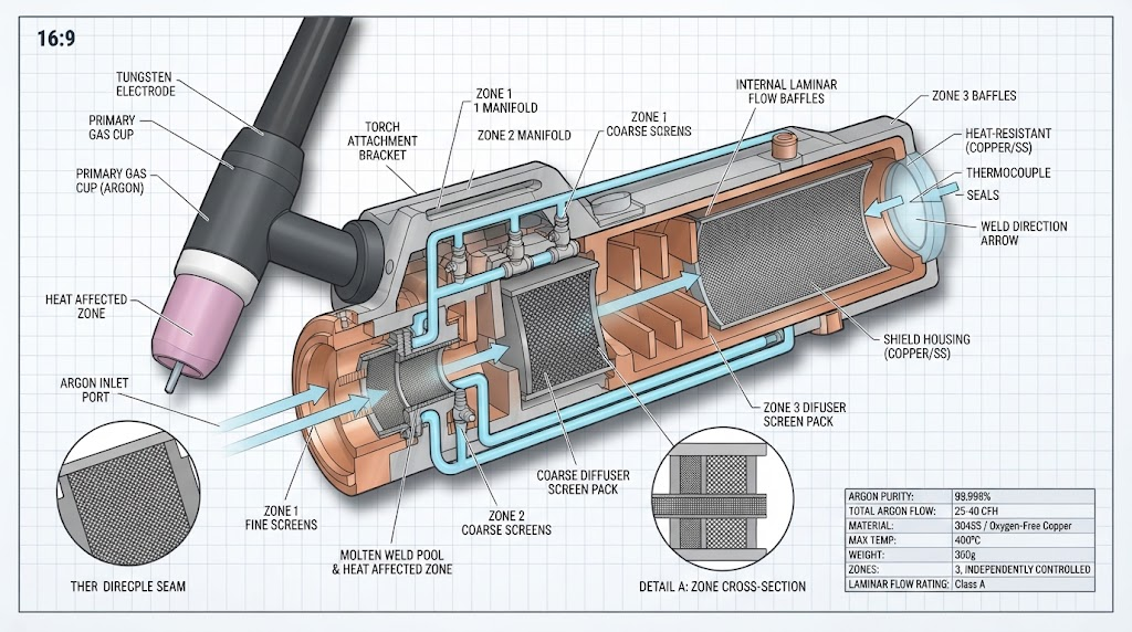
High-speed trailing shields should incorporate internal water-cooling channels and independent dual-stage flow diffusers. Stage 1 (adjacent to the torch) supplies 25 to 35 L/min of UHP argon to handle initial solidification, while Stage 2 delivers 15 to 20 L/min to protect the HAZ down through the critical 400°C threshold.
Grade-Specific Shielding Vulnerabilities: CP Titanium vs. Ti-6Al-4V (Grade 5)
Different titanium alloy grades display varying sensitivities to atmospheric contamination during welding.
Commercially Pure (CP) Titanium (Grades 1, 2, 3, and 4) consists of an all-alpha phase microstructure. Interstitial oxygen absorption raises tensile yield strength while reducing elongation. CP Grade 2 can tolerate minor interstitial uptake without immediate cracking, though it will show reduced ductility in bend testing.
In contrast, alpha-beta alloys like Grade 5 Ti-6Al-4V Fabrication Services and Grade 23 (Ti-6Al-4V ELI) are much more sensitive to contamination. When welding Grade 5, rapid cooling through the beta-transus temperature (~995°C / 1823°F) generates transformed acicular alpha (martensitic α') within the fusion zone.
Interstitial contamination in Grade 5 welds stabilizes high-hardness alpha formations, creating localized stress risers that lead to delayed micro-cracking under cyclic loading. For Grade 5 aerospace structures, interpass temperatures must remain below 120°C (248°F), and gas purging must hold oxygen levels strictly below 10 ppm throughout the process.
The China Titanium Factory Laminar Inert Purge System (LIPS) Protocol
To eliminate shielding failures and ensure consistent weld quality, our production facilities utilize the Laminar Inert Purge System (LIPS) across all mechanized TIG and automated PAW operations.
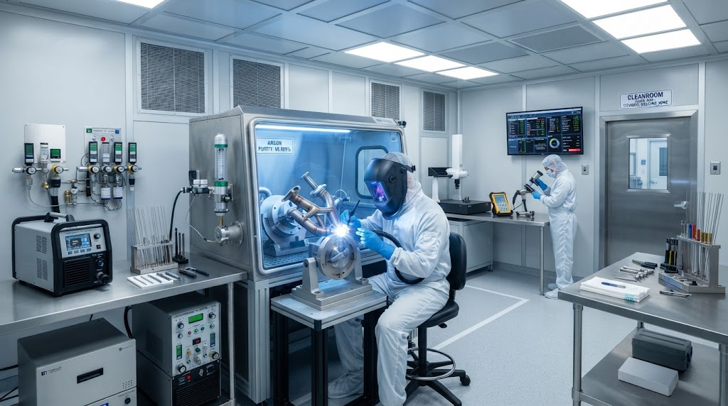
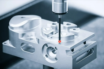
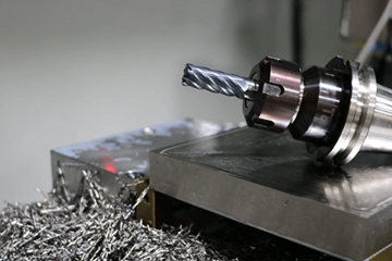
Sub-0.05 mm Precision Edge Preparation: All joint interfaces undergo CNC milling with dedicated, non-contaminated carbide tooling to achieve square butt fit-ups with tolerances under 0.05 mm. Eliminating edge burrs and gaps avoids gas micro-turbulence and air entrapment during keyhole initiation.
Multi-Point Zirconia Sensor Purge Verification: Purge chambers and backing bars use calibrated zirconia oxygen analyzers. The welding power source remains electronically interlocked until oxygen levels drop below 8 ppm across all sample points.
Dynamic Dual-Phase Shielding Gas Modulation: Closed-loop mass flow controllers adjust primary, trailing, and root gas flow rates based on real-time travel speed and infrared thermal feedback, maintaining laminar conditions across all weld phases.
100% Microhardness Mapping & Alpha-Case Verification: Every production lot undergoes non-destructive microhardness mapping. Hardness increases exceeding 20 HV (Vickers 100g load) relative to base metal trigger metallographic cut-and-etch validation per ASTM E384.
Industrial Comparison & Economic Selection: TIG vs. PAW
Selecting between GTAW and PAW involves balancing capital equipment costs against production volume, plate thickness, and joint configuration requirements.
| Evaluation Parameter | Manual / Mechanized TIG (GTAW) | Keyhole Plasma Arc (PAW) |
|---|---|---|
| Single-Pass Thickness Limit | Up to 3.0 mm (Square butt) | Up to 12.7 mm (Single pass, zero bevel) |
| Edge Preparation Needs | V-groove / U-groove above 3.5 mm | Square butt milling (<0.05 mm gap) |
| Tungsten Inclusion Risk | Moderate (Electrode exposure) | Zero (Protected internal electrode) |
| Argon Consumption Rate | Low to Moderate (20–40 L/min total) | High (50–85 L/min total system flow) |
| Initial Capital Investment | Low ($5,000 – $25,000 USD) | High ($70,000 – $250,000 USD) |
| Best Industrial Fit | Piping spools, thin sheet, field repair | Pressure vessels, heavy plate, long longitudinal seams |
For complex subassemblies with variable wall thicknesses, manual GTAW provides the agility required for tight joint access. For longitudinal seam welding on large titanium vessels and Precision CNC Titanium Machined Components, automated Keyhole PAW reduces multi-pass labor by up to 75% while eliminating the risk of tungsten inclusions.
Post-Weld Discoloration & Metallurgical Quality Assurance
Surface oxidation color provides immediate visual feedback on the effectiveness of the shielding setup. While surface color indicates the temperature at which oxygen exposure occurred, it must be evaluated alongside microhardness testing to confirm structural integrity.
| Surface Appearance | Oxidation Level | Exposure Temp Range | Hardness Increase (HV) | Disposition & Corrective Action |
|---|---|---|---|---|
| Bright Silver | None (Pristine) | < 400°C (752°F) | 0 – 5 HV | Full Acceptance: Class A (Aerospace & Critical Process) |
| Light Straw / Pale Gold | Very Low | 400°C – 500°C | 5 – 15 HV | Acceptable: Class B industrial use; stainless wire brush removal |
| Dark Straw / Bronze | Moderate | 500°C – 600°C | 15 – 30 HV | Marginal: Rejected for critical service; requires mechanical grinding and re-inspection |
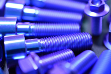
| Peacock Blue / Violet | Severe | 600°C – 700°C | 30 – 60 HV | Rejected: Alpha-case layer present; complete mechanical excavation required |
| Gray / Flaky White Powder | Catastrophic (TiO2) | > 700°C (>1292°F) | > 80 HV | Critical Failure: Deep interstitial embrittlement; cut out entire joint |
A bright silver weld confirms the metal remained protected until cooling below 400°C. If a weld turns blue or gray, contamination occurred while the material was at high temperature. In these cases, light surface pickling is insufficient, as interstitial oxygen will have diffused deep into the fusion zone, necessitating complete mechanical removal of the affected area.
Frequently Asked Questions
Can you weld titanium without a trailing shield?
No, you cannot produce code-compliant titanium welds without a trailing shield unless the entire component is enclosed inside an inert gas chamber (glovebox) with oxygen levels below 10 ppm. Standard torch cups leave the solidified metal exposed to air above 427°C, resulting in immediate alpha-case embrittlement.
Why is 99.999% UHP Argon required over standard industrial argon?
Standard industrial argon (99.99% pure) can contain up to 100 ppm of moisture and oxygen. Titanium absorbs these impurities at elevated temperatures. Grade 5.0 UHP Argon (99.999% pure) guarantees less than 2 ppm oxygen and a dew point below -65°C, preventing interstitial hardening and fatigue failure.
What causes root underbead blowout in Keyhole PAW?
Root underbead blowout occurs when the high-velocity plasma gas exiting the keyhole is trapped inside a non-vented backing bar channel. The resulting backpressure destabilizes the molten underbead, causing expulsion. Using dual-chamber backing bars with engineered exhaust vents eliminates these pressure spikes.
What is the acceptable oxygen level in a titanium purge chamber before welding?
Per AWS D1.9 and aerospace fabrication standards, the oxygen concentration within a root purge channel or glovebox must measure below 50 ppm (0.005%) for commercial components, and strictly below 10 ppm for critical aerospace, medical, and rotating subassemblies before striking the arc.