| Grade & Chemistry: | Ti-6Al-4V Grade 5 (UNS R56400 / W.Nr. 3.7165) |
| Key Standard Specs: | SAE AMS 2488D (Anodic Coatings for Titanium), ASTM F86 (Surface Preparation and Marking of Metallic Surgical Implants), ISO 8080 (Anodic Treatment of Titanium and Titanium Alloys), ASTM B348 / AMS 4928 |
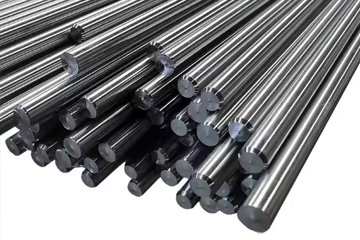
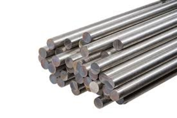
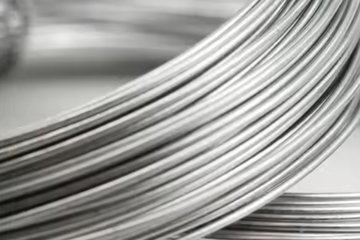
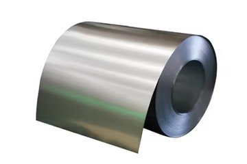
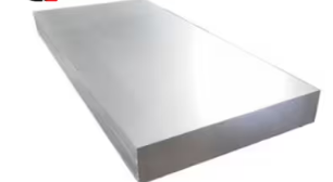
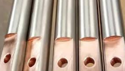
| Delivery Forms: | Centerless Ground Bars (h7/h8/h9), Precision Billet & Wire, Finished CNC Turned/Milled Components |
| Core Mechanical Benchmarks: | Refractive Index of Rutile/Anatase Oxide (n): 2.1 to 2.6 (Wavelength Dependent) | Oxide Growth Rate per Volt: 1.6 to 2.0 nm / V DC | Interference Color Thermal Breakdown Threshold: 300°C (572°F) Sustained Service | Substrate Dimensional Growth (Δt): < 0.20 μm (< 0.000008 in) |
| Machinability Profile: | 22% of B1112 Steel. Surface roughness prior to anodizing must achieve Ra ≤ 0.4 μm to guarantee optical clarity and uniform light refraction. |
Titanium anodizing colors are produced entirely through optical thin-film interference within a transparent, dielectric titanium dioxide (TiO2) surface layer, rather than chemical dyes or pigments. When exposed to an electrolytic bath under an applied direct-current potential, oxygen ions migrate into the metal matrix to grow an amorphous to semi-crystalline oxide film ranging from 10 to 300 nanometers. The observed hue depends entirely on the physical thickness of this boundary layer, which selectively cancels and amplifies specific wavelengths of incident light via constructive and destructive interference.
Unlike aluminum anodizing, which builds a porous, honeycomb aluminum oxide structure that absorbs liquid dyes, titanium anodizing is non-porous and electrochemically self-terminating. The naturally formed passivation barrier on titanium measures approximately 2 to 5 nm under ambient atmospheric conditions. Applying direct-current potential forces forced ionic transport across the dielectric barrier, steadily thickening the barrier film until the internal resistance of the TiO2 matches the driving voltage.
The resulting perceived color is a structural property. Incident white light encounters two interfaces: the air-to-titanium-dioxide interface and the titanium-dioxide-to-titanium-substrate interface. Part of the light wave reflects off the outer oxide surface, while the transmitted portion travels through the dielectric layer, reflects off the metallic titanium below, and exits back into the surrounding medium.
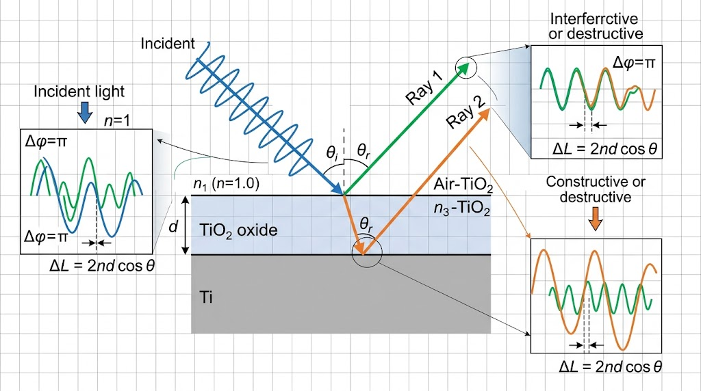
Light wave phase shifting within the dielectric medium governs the exact optical path difference (OPD). The mathematical conditions for constructive wave interference in a non-absorbing dielectric thin film are expressed by the adjusted optical equation:
2 × n × d × cos(θ) = (m - ½) × λ
Where:
n = Refractive index of the anodized TiO2 film (typically 2.1 to 2.6 depending on anatase/rutile crystal ratios and operational wavelength).
d = Physical thickness of the oxide layer in nanometers (nm).
θ = Refraction angle inside the titanium dioxide film, determined by Snell’s Law: sin(θincident) = n × sin(θ).
m = Order of constructive interference (integers: 1, 2, 3...).
λ = Spectral wavelength of the amplified color in nanometers.
The term (- ½) accounts for the 180° (π radians) phase inversion that occurs when light reflects off a medium with a higher refractive index than the incident medium (nair ≈ 1.0 < nTiO2 ≈ 2.4). At the second interface (TiO2 to Ti substrate), the complex refractive index of the titanium metal matrix creates an additional minor phase change, producing slight chromatic shifts.
In industrial production, the growth of the TiO2 dielectric film follows a linear anodizing ratio of 1.6 to 2.0 nm per applied direct-current volt (V DC). Because the optical path difference dictates which wavelength emerges in phase, stepping the electrical potential in precise increments modulates physical layer growth at the atomic scale, traversing the interference spectrum from pale yellow through magenta and high-order green.
Because bath temperature, electrolyte composition, and substrate alloy composition influence dissolution rates, process engineers rely on empirical DC voltage curves calibrated against CIE Lab* coordinates. China Titanium Factory regulates rectifiers to within ±0.2 V DC using ripple-filtered switch-mode power supplies to lock in optical repeatability across production batches of our ASTM B348 titanium round bar inventory.
| Potential (V DC) | Oxide (nm) | Nominal Color Hue | Interference Order | CIE L* | CIE a* | CIE b* |
|---|---|---|---|---|---|---|
| 12 – 14 | 22 – 26 | Pale Bronze / Straw | 1st Order | 68.4 | +2.1 | +16.3 |
| 18 – 22 | 34 – 42 | Deep Bronze / Brown | 1st Order | 54.1 | +8.7 | +12.4 |
| 25 – 28 | 48 – 54 | Aubergine / Violet | 1st Order | 42.3 | +14.2 | -18.1 |
| 30 – 35 | 58 – 68 | Cobalt Blue | 1st Order | 46.8 | -2.4 | -32.6 |
| 40 – 46 | 76 – 88 | Sky Blue / Cyan | 1st Order | 62.5 | -16.1 | -19.4 |
| 52 – 58 | 98 – 110 | Bright Yellow / Gold | 2nd Order | 74.2 | +1.2 | +44.8 |
| 62 – 68 | 118 – 130 | Rose / Magenta | 2nd Order | 56.7 | +28.5 | +4.3 |
| 72 – 80 | 136 – 152 | Teal / Cyan-Green | 2nd Order | 63.1 | -22.7 | +11.2 |
| 85 – 95 | 160 – 180 | Emerald / Kelly Green | 2nd / 3rd Order | 66.8 | -28.3 | +26.5 |
| 100 – 110 | 190 – 210 | Dusty Pink / Pale Magenta | 3rd Order | 58.3 | +16.4 | +2.1 |
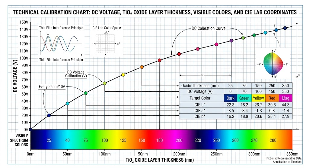
Procurement specifications frequently request "fire-engine red" or "pitch black" color anodized titanium. In metallurgical practice, producing saturated red or pure black finishes via Type III electrolytic thin-film anodization is physically impossible.
Thin-film interference cannot produce true red because of the broad spectral absorption profile of titanium dioxide and the distribution of visible light wavelengths. When the TiO2 thickness approaches the dimension required to reflect red light (approx. 650 to 700 nm), higher-order interference bands overlap simultaneously within the blue and violet wavelengths (approx. 400 to 450 nm). As a result, the perceived color appears as magenta, rose, or pinkish-purple rather than monochromatic primary red.
True black is similarly unattainable through standard Type III electrolytic growth. The TiO2 dielectric layer is optically clear and non-absorbing. Black requires complete, broadband absorption across all visible wavelengths (380 to 750 nm) with zero reflection. Because interference relies entirely on phase reflections from the metallic boundary, the substrate will always reflect a high proportion of incident photons.
| Surface Technology | Process Chemistry | Coating Thickness | Hardness (HV) | Dimensional Growth |
|---|---|---|---|---|
| Type III Anodizing | Electrolytic Thin-Film TiO2 | 0.02 – 0.25 μm | ≈ 400 – 600 | Negligible (< 0.1 μm) |
| PVD (TiAlN / AlTiN) | Physical Vapor Deposition | 1.5 – 4.0 μm | 2,800 – 3,400 | Direct coating build |
| Diamond-Like Carbon (DLC) | Plasma CVD Carbon Lattice | 1.0 – 3.0 μm | 2,000 – 5,000 | Direct coating build |
| PEO / MAO (Black Oxide) | Micro-Arc Conversion in Phosphate | 5.0 – 25.0 μm | 800 – 1,400 | Significant (50% of layer) |
When engineering designs demand matte black or deep luster surfaces on titanium, design engineers should bypass standard electrolytic anodizing. Instead, specify thin-film Diamond-Like Carbon (DLC), vacuum PVD arc evaporation, or Plasma Electrolytic Oxidation (PEO) to achieve full visual absorption while imparting wear resistance.
A frequent QA issue is the visible shift in color saturation when identical anodizing voltages are applied across different titanium grades. Commercially Pure Grade 2 Titanium produces vivid, highly saturated hues, whereas alpha-beta alloys like Ti-6Al-4V Grade 5 yield muted, pastel, or brownish-shifted tones.
This chromatic variance stems from alloy microstructures and phase partitioning. CP Grade 2 consists entirely of an equiaxed hexagonal close-packed (HCP) alpha (α) phase, which forms a uniform, stoichiometric TiO2 film across the grains. In contrast, Ti-6Al-4V contains both the HCP α-phase and a body-centered cubic (BCC) beta (β) phase stabilized by 4% vanadium.
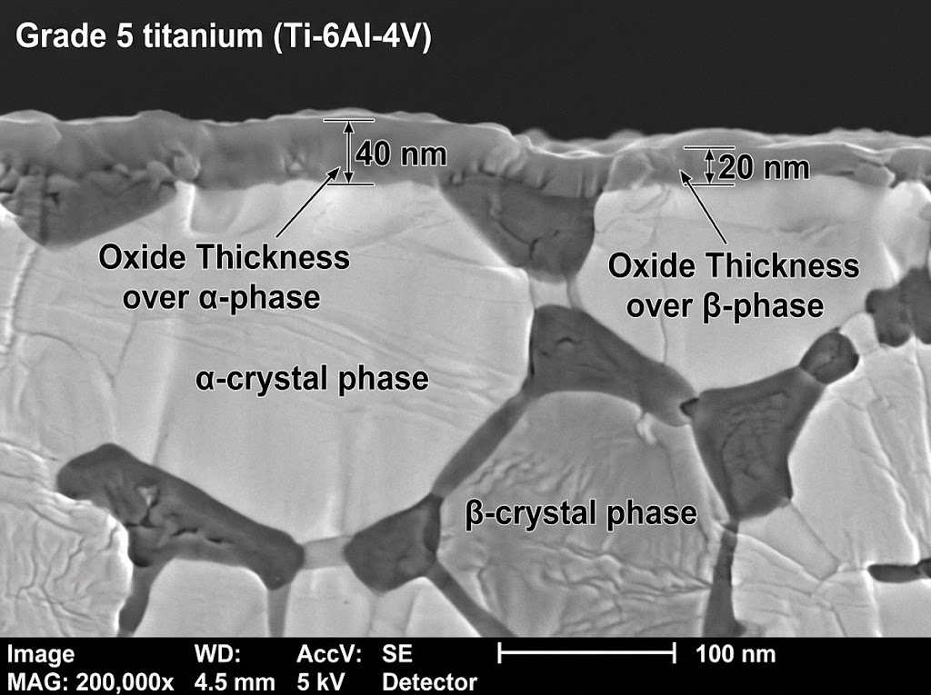
During electrolytic oxidation, the beta grains dissolve and anodize at different electrochemical reaction rates than the neighboring alpha grains. Vanadium segregates into the beta phase, where it oxidizes into non-stoichiometric vanadium oxides (V2O5 and VO2). These vanadium oxides enter the titanium dioxide lattice, introducing localized bandgap defects and elevated optical absorption coefficients.
The resulting oxide layer features microscopic thickness variations between adjacent α and β grains. This localized step-height disparity scatters reflected light incoherently, degrading specular reflectance and washing out vibrant colors. For medical implants requiring both high mechanical strength and precise color differentiation, our facility processes medical grade Ti-6Al-4V ELI bar stock with tight interstitial controls (O ≤ 0.13%, Fe ≤ 0.25%) to preserve uniform grain boundaries and maximize interference clarity.
Achieving batch-to-batch color consistency requires tight regulation of bath conductivity, pH, and electrolyte chemistry. Three primary formulations dominate production environments:
Trisodium Phosphate (TSP, Na3PO4): Mildly alkaline bath (3% to 8% concentration by weight, pH 9.0 to 11.5). Excellent for consistent Type III color generation. Produces low etching rates and clear interference colors with minimal handling hazards.
Phosphoric Acid (H3PO4): Acidic electrolyte (5% to 15% concentration by volume, pH 1.0 to 2.0). Provides lower bath electrical resistance, enabling rapid oxide growth. Commonly specified for aerospace hardware due to clean residual rinsing and high oxide dielectric breakdown strength.
Sulfuric Acid (H2SO4): Low concentration (1% to 5% by volume). Offers fast processing speeds but narrows the voltage window, making precise color targeting more difficult.
Operating rectifiers must supply switch-mode direct current with an AC ripple factor of less than 1.0% RMS. High ripple components cause phase-interference distortion, as voltage oscillations disrupt uniform nanometer growth. Current density is maintained at 0.5 to 2.0 A/dm2 during immersion.
Because electrolytic oxidation is exothermic, local bath temperatures rise quickly around high-surface-area loads. China Titanium Factory uses closed-loop recirculating chillers to hold electrolyte baths at 20°C ± 0.5°C. Shifts larger than ±2.0°C alter the dissolution-to-growth balance, shifting final hues across production runs.
Anodizing cannot conceal substrate surface irregularities; it amplifies underlying microscopic defects. Preparing components requires alkaline degreasing followed by a regulated chemical etch (pickling) to strip native room-temperature oxides, drawing scale, and micro-machining smearing.
Substandard pickling introduces risks of nascent hydrogen embrittlement. When titanium reacts with hydrofluoric acid (HF) in improperly balanced baths, atomic hydrogen generates rapidly at the alloy surface:
2 Ti + 6 HF → 2 TiF3 + 3 H2↑
If nitric acid (HNO3) is deficient, atomic hydrogen diffuses into the interstitial lattice, precipitating brittle titanium hydride (δ-hydrides) needles that cause premature brittle failure under sustained mechanical loads. To prevent hydrogen absorption, pre-treatment baths must maintain a strict volumetric ratio:
HNO3 : HF ≥ 10 : 1 (by volume, per ASTM B600 guidelines)
The high nitric acid concentration acts as a strong oxidizer, immediately passivating the metal and converting nascent hydrogen into water before it can dissolve into the substrate core. Chemical lots undergo periodic testing per ASTM E1447 via inert gas fusion thermal conductivity detection, ensuring bulk interstitial hydrogen levels stay securely below 125 ppm (and under 50 ppm for mission-critical flight hardware).
While low-voltage anodizing (under 50 V DC, covering bronze through cyan) has a negligible effect on substrate mechanical performance, high-voltage processing (85 V to 110 V DC, producing emerald greens and higher-order pinks) introduces serious fatigue considerations.
As the potential exceeds the dielectric breakdown voltage of the growing TiO2 barrier (typically between 85 and 95 V depending on bath conductivity), the film can no longer insulate the substrate. Localized spark discharges, or micro-arcing, puncture the oxide film.
| Target Color Regime | Voltage Window | Dielectric State | Surface Morphology | HCF Debit (107 Cycles) |
|---|---|---|---|---|
| Straw / Bronze / Blue | 12 – 45 V DC | Uniform Amorphous | Pore-free, planar | < 2% (Statistically Insignificant) |
| Gold / Rose / Magenta | 50 – 75 V DC | Stable Semi-Crystalline | Isolated crystalline nodes | 2% – 5% Marginal Debit |
| Teal / High-Order Green | 85 – 110 V DC | Dielectric Breakdown Threshold | Micro-fissures, localized pitting | 10% – 15% Reduction in Endurance Limit |
These dielectric discharge events generate microscopic volcanic pits and fine surface cracks. Under cyclic fatigue loading, these micro-voids act as stress concentration notches, accelerating fatigue crack initiation.
To eliminate high-voltage micro-arcing on fatigue-critical aerospace parts, our processing protocol applies programmed ramp rates (e.g., 0.5 V/second) alongside current-limiting thresholds. This gradual ramp prevents voltage overshoots, enabling stable high-order green generation without triggering dielectric breakdown.
Procurement documents must clearly delineate between cosmetic/identification anodizing and anti-galling functional surface conversions. Conflating these two distinct processing standards remains an expensive, common drafting oversight in engineering packages.
| Specification Metric | SAE AMS 2488D Type II | SAE AMS 2488D Type III | ASTM F86 / ISO 8080 |
|---|---|---|---|
| Primary Engineering Intent | Anti-galling, wear resistance, lubrication key | Color coding, visual size identification | Biocompatible passivation, implant sizing |
| Electrolytic Chemistry | Alkaline (pH ≥ 13.0), hot bath | Acidic or mild phosphate (TSP) | High-purity aqueous phosphate / borate |
| Surface Morphology | Thick, porous, non-reflective conversion | Dense, thin-film non-porous dielectric | Amorphous thin-film, high purity |
| Appearance / Palette | Matte battleship grey / charcoal | Full interference spectrum (Bronze to Green) | Calibrated color spectrum (Pink/Blue/Green) |
| Dimensional Growth (Δt) | 1.0 to 5.0 μm (0.00004 to 0.0002 in) | < 0.20 μm (< 0.000008 in) | < 0.15 μm (< 0.000006 in) |
| Lubricant Retention | High (acts as mechanical carrier for MoS2) | Low (smooth specular surface) | None (direct tissue contact) |
AMS 2488 Type II is a thick, porous conversion coating engineered to resolve titanium’s severe galling and thread-seizure tendencies under sliding contact. It provides no aesthetic color value, presenting exclusively as a dull grey. Conversely, AMS 2488 Type III and ASTM F86 specify non-porous thin-film interference oxidation intended for visual assembly identification, surgical line separation, or corrosion passivation.
Medical instruments, bone plates, and orthopedic fixators utilize color anodization for instant visual identification of screw diameters and left/right drill templates. Maintaining optical calibration over repeated hospital reprocessing cycles is a non-negotiable biocompatibility and patient-safety baseline.
Color degradation during moist autoclave sterilization (134°C saturated steam at 3.0 bar pressure) occurs via hydrothermal oxide hydration. Under high-temperature pressurized steam, amorphous TiO2 absorbs hydroxyl groups (OH-), slowly converting into hydrated titania complexes. This structural shift alters the film's refractive index (n) and triggers a visible shift: ΔE*ab > 2.5 after 50 to 100 cycles.
In aerospace applications, thermal limitations present absolute operating boundaries. Interference colors remain mechanically intact but experience permanent chromatic drift when exposed to continuous environments above 300°C (572°F).
At these elevated temperatures, atmospheric oxygen diffuses directly through the oxide film into the underlying titanium substrate, steadily thickening the barrier layer via thermal oxidation. A part anodized to 30 V blue (approx. 60 nm) held at 400°C will shift toward gold, magenta, and eventually break down into a muddy, non-reflective tan within hours.
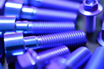
Critical structural fasteners used in commercial aviation demand conflicting performance characteristics across a single component. Threaded shanks require high-lubricity, anti-galling protection under heavy preload torque, while bolt drive heads require vibrant, fool-proof color identification for line technicians to confirm bolt diameter and length during airframe assembly.
China Titanium Factory addresses this by manufacturing custom aerospace titanium fasteners and bolts utilizing a dual-stage masking and conversion procedure:
Bulk Primary Conversion: The fastener undergoes hot alkaline AMS 2488 Type II conversion across its entire surface, forming an anti-galling, micro-porous grey base layer.
Precision Elastomeric Masking: High-precision EPDM or fluorosilicone masking caps seal the threaded zones. Thread lead chamfers must be masked cleanly to maintain tight thread-pitch tolerances without interference.
Controlled Chemical Strip: Unmasked bolt heads are exposed to a rapid, temperature-regulated fluoronitric etch to strip the Type II coating back to bare metal without removing base material.
Secondary Color Electrolysis: Parts are submerged in a secondary Type III electrolyte bath, driving voltage up to target color bands (e.g., 32 V blue for 6 mm shank, 54 V gold for 8 mm shank).
Because Type III oxide growth consumes less than 0.05 μm of base titanium, thread pitch dimensions remain completely unaffected, eliminating the need for chasing or secondary thread-rolling operations.
To eliminate color variation across high-volume production, China Titanium Factory engineers developed The China Titanium Factory Dual-Stage Optical Stabilization Protocol. This methodology guarantees a color variance limit of ΔE*ab ≤ 0.8 across separate production heats.
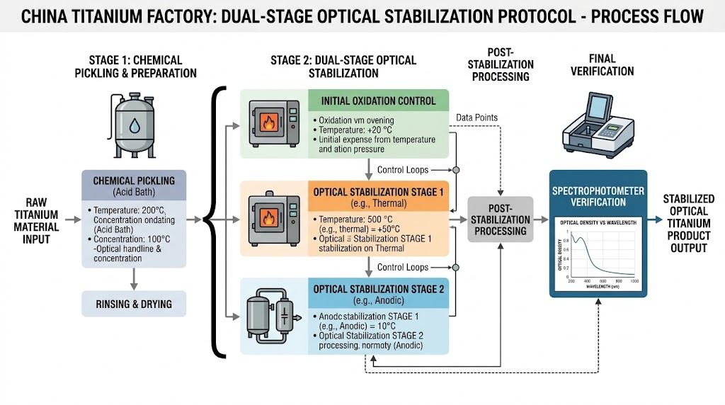
The protocol deploys three strictly controlled production phases:
Phase 1: Controlled Micro-Etch & Hydride Clearing: Feedstock components undergo automated acid pickling in an 11:1 HNO3:HF bath maintained at 25°C ± 1°C for 45 seconds. This removes 3 to 5 μm of surface-disturbed metal, establishing a pristine baseline surface roughness (Ra ≤ 0.35 μm) and removing ambient room oxides.
Phase 2: Closed-Loop Pulse-Rectified Oxidation: Components are transferred into a temperature-stabilized (20.0°C ± 0.2°C) ammonium phosphate electrolyte. Electrical potential is delivered via switch-mode rectifiers using a stepped-pulse profile: an initial 50 ms strike followed by a 0.25 V/s ramp to peak voltage. This suppresses local micro-arcing and maintains uniform dielectric growth across complex geometries.
Phase 3: Hydrothermal Passivation & Ultrasonic Sealing: Immediately following immersion, parts enter a cascade rinse of ASTM Type II deionized water (< 0.1 μS/cm conductivity), followed by immersion in 90°C degassed deionized water for 180 seconds. This stabilizes the outer nanometer of the amorphous oxide without inducing the phase changes that distort thin-film interference.
Every lot is verified using an industrial sphere spectrophotometer (D65 illuminant, 10° observer) to validate that spectral readings align with master CAD tolerance bands prior to lot release.
Titanium anodizing has clear mechanical and chemical boundaries. Disregarding these operational limits will result in surface breakdown or component failure:
Dry Chlorine Hazard: Anodized titanium components must never be exposed to dry chlorine gas (containing less than 1.5% moisture). The absence of water prevents rapid self-healing passivation, leading to pyrophoric, highly exothermic reactions and spontaneous combustion.
Red Fuming Nitric Acid: Exposure to anhydrous red fuming nitric acid creates explosive, shock-sensitive ignition risks due to rapid intergranular oxidation.
Galvanic Isolation: When pairing color-anodized titanium assemblies with aluminum or carbon steel in marine environments, designers must specify dielectric isolators (e.g., PTFE or Delrin washers). Titanium serves as a noble cathode, driving aggressive galvanic corrosion of adjoining active metals.
Stress Corrosion Cracking (SCC): During pre-machining operations, machine shops must prohibit chlorinated cutting fluids. Residual chloride ions remaining on the surface under tensile operational stresses can initiate catastrophic Stress Corrosion Cracking at sustained temperatures above 250°C.
Before parts enter anodizing lines, upstream surface preparation during CNC turning and milling is paramount. Our precision CNC titanium machining services maintain surface finishes of Ra ≤ 0.4 μm (16 μin). Diffuse light scattering on rough surfaces (Ra > 0.8 μm) destroys specular thin-film interference, resulting in lifeless, washed-out hues regardless of applied electrical potential.
In aerospace and surgical sectors, aesthetic consistency must be backed by rigorous metallurgical traceability. China Titanium Factory implements comprehensive quality control dossiers for all mill deliveries and machined components.
Raw materials are melted exclusively via Vacuum Arc Remelting (VAR, 2x or 3x melt cycles) or Electron Beam Cold Hearth Remelting to eliminate High-Density Inclusions (HDI) and brittle hard-alpha nitrogen inclusions. Internal structural integrity is verified via AMS 2631 Class AA (longitudinal and shear wave) ultrasonic testing.
| Inspection Domain | Governing Standard | Acceptance Criteria |
|---|---|---|
| Chemical & Physical Verification | EN 10204 Type 3.1 | Full heat traceability, interstitial limits verified |
| Internal Defect Detection | AMS 2631 Class AA / ASTM E114 | Zero recordable voids, inclusions, or unbonded seams |
| Hydrogen Interstitial Gas Analysis | ASTM E1447 | Bulk H2 ≤ 125 ppm (≤ 50 ppm for flight critical) |
| Neutral Salt Spray Corrosion | ASTM B117 | 336 hours continuous fog exposure without pitting |
| Oxide Film Adhesion Testing | ASTM D3359 Cross-Hatch / Tape | Classification 4B/5B, zero coating peel or flaking |
| Surface Spectrophotometry | ASTM E1347 / CIE 1976 Lab | Batch-to-batch ΔEab ≤ 0.8 against master sample |
For international transit, finished components receive meticulous barrier packaging. Anodized ground stock and parts are fitted with non-abrasive protective polyethylene mesh sleeves, double-sealed in desiccated vapor-barrier bags, and secured within robust IPPC ISPM 15 heat-treated plywood crates to prevent container transit humidity from degrading surface chemistry.
Evaluating titanium grades for critical service conditions? Connect directly with our metallurgical and CNC engineering team to review 2D/3D part drawings, verify EN 10204 3.1 certification dossiers, or request ultrasonic testing records.
MTC 3.1 Verification: Full heat melt traceability & spectrographic chemical batch reports.
DFM & Tolerance Review: Precision centerless grinding (h7/h8/h9) & toolpath feasibility analysis.
NDT Compliance: AMS 2631 Class AA/A ultrasonic inspection and liquid penetrant testing certs.
Anodizing voltage is only one parameter governing thin-film growth. Final color is determined by optical thickness, which depends on electrolyte chemistry, bath temperature, and alloy phase distribution. A 30 V setpoint in an uncooled TSP bath will produce a completely different optical thickness than a 30 V setpoint in phosphoric acid. Furthermore, surface finish variations (Ra > 0.8 μm vs. Ra ≤ 0.2 μm) scatter light differently. Precise procurement callouts must specify CIE Lab coordinates (ΔEab ≤ 1.0) rather than simple direct current voltages.
The dimensional impact of Type III color anodization is practically negligible. The oxide film measures between 0.02 and 0.25 μm (0.000001 to 0.000010 in). Because approximately 50% of this layer grows inward into the parent metal, net outward surface growth (Δt) is less than 0.12 μm (< 0.000005 in). High-precision aerospace threads, internal bearing bores, and ground surfaces require no post-coating dimensional allowances or re-tapping.
No. While TiO2 exhibits moderate micro-hardness, thin-film Type III coatings are far too thin to withstand sliding, friction, or continuous mechanical wear. For anti-galling and dry lubrication retention, engineers must specify AMS 2488 Type II, which produces a much thicker (1 to 5 μm), porous conversion layer engineered specifically for friction applications.
Yes, but with strict controls. Stripping requires brief immersion in a dilute hydrofluoric/nitric acid bath or proprietary ammonium bifluoride solution. This chemical stripping inevitably removes 2 to 5 μm of base substrate metal. On components with critical micro-tolerances (±0.005 mm), stripping must be carefully evaluated to ensure it does not compromise key dimensions or cause thread fit violations.
Procuring precision-anodized titanium hardware demands structured communication to avoid mismatched expectations and non-conforming lots. We implement a direct 3-step technical pathway for all incoming production requests:
Step 1: Engineering Data Submission: Provide native 2D/3D part drawings (.STEP, .IGES, or .PDF) clearly indicating anodizing specifications (AMS 2488 Type II vs. Type III, ASTM F86), target CIE Lab* coordinates or standard color swatches, designated electrical racking contact zones, and any surface masking boundaries.
Step 2: DFM & Metallurgical Review: Our engineering team reviews the drawing within 24 hours. We evaluate base alloy grain structure, calculate required pre-treatment acid-etch ratios, define pulse-ramping sequences to protect fatigue life, and confirm tooling rack placements to prevent contact shadowing.
Step 3: First-Article Sample Validation: We produce and ship an expedited 5-piece First Article Inspection (FAI) sample lot complete with full EN 10204 Type 3.1 chemical/mechanical test certificates, inert gas fusion hydrogen verification reports, and spectrophotometer color validation dossiers for assembly sign-off.



Contact Us
Room 21003, 10th Floor, Unit 2, Building 1, Xianning International Plaza, No.29 Xianning West Road, Beilin District, Xi'an City
Copyright © Xi'an Shiguang Jingyan Technology Co., Ltd. All Rights Reserved.