



















The Science Behind Titanium Anodizing: Thin-Film Interference & Oxide Kinetics
Titanium anodizing is an electrolytic oxidation process that converts the base metal surface into a controlled, coherent layer of amorphous titanium dioxide (TiO₂). Applying a direct current (DC) voltage across an electrolytic bath forces oxygen ions to migrate to the titanium substrate (anode), driving oxide growth that terminates when the dielectric resistance matches the applied electrical potential.
Unlike aluminum anodizing, titanium anodizing does not rely on open porous structures that trap organic dyes or pigments. The perceived colors stem entirely from thin-film optical interference.
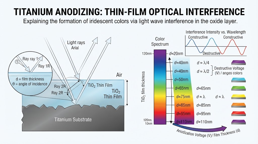
When ambient white light strikes the anodized surface, a portion of the light wave reflects off the outer boundary of the transparent oxide film. The remaining light refracts through the film, reflects off the underlying base titanium substrate, and exits back into the air.
Because the refracted light travels an additional distance equal to twice the film thickness, its phase shifts relative to the surface reflection. When specific wavelengths align out of phase, destructive interference cancels those colors; wavelengths that emerge in phase undergo constructive interference, intensifying the observed hue.
Dielectric Film Kinetics: The refractive index of an amorphous anodic TiO₂ layer ranges between n = 2.2 and n = 2.6. The film thickness directly dictates which light wavelengths undergo destructive phase cancellation according to the relation: 2nd = (m + ½)λ, where n is the refractive index, d is film thickness in nanometers, m is the interference order, and λ is the target wavelength.
Titanium Anodizing Voltage Spectrum & Oxide Thickness Data Chart
Direct current voltage precisely controls the thickness of the barrier-type titanium dioxide layer. In our manufacturing experience at China Titanium Factory, the anodic oxide layer grows at approximately 1.5 to 3.0 nanometers per applied volt (nm/V), depending on electrolyte conductivity, bath temperature, and specific alloy chemistry.
Operating beyond 105V to 110V initiates localized dielectric breakdown, causing micro-arcing that degrades optical uniformity and yields an irregular, burnt-grey finish.
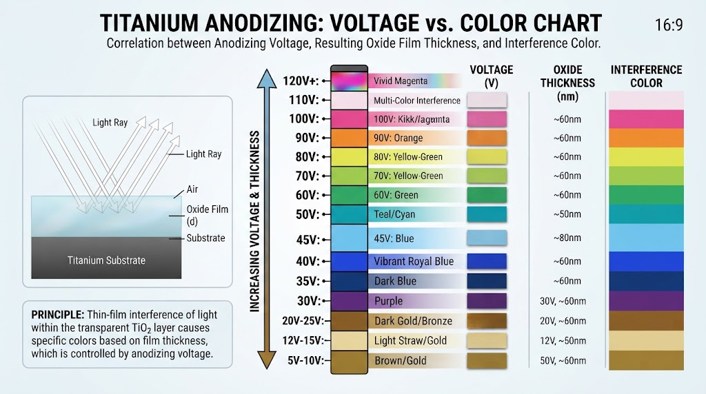
| Applied DC (V) | Oxide Thickness (nm) | Primary Color Produced | Interference Order | Technical Application |
|---|---|---|---|---|
| 12 – 15 V | 25 – 35 nm | Bronze / Pale Yellow | 1st Order | Low-friction fastener coding |
| 22 – 28 V | 45 – 60 nm | Deep Purple / Violet | 1st Order | Medical tool identification |
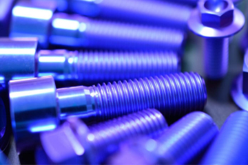
| 30 – 38 V | 65 – 80 nm | Dark Blue / Royal Blue | 1st Order | Orthopedic bone screw sizing |
| 45 – 52 V | 95 – 115 nm | Light Sky Blue / Ice Blue | 1st Order | Aerospace bracket coding |
| 58 – 65 V | 125 – 145 nm | Bright Gold / Straw | 2nd Order | Implantable device components |
| 68 – 78 V | 150 – 175 nm | Rose / Magenta / Pink | 2nd Order | Precision surgical instruments |
| 85 – 95 V | 185 – 215 nm | Teal / Vibrant Green | 2nd Order | Custom motorsport fixturing |
| 100 – 108 V | 220 – 240 nm | Lime Green / Opal Pink | 3rd Order | High-voltage verification targets |
Metallurgical Variables: Anodizing CP Grade 2 vs. Ti-6Al-4V Grade 5
Alloy metallurgy directly dictates how an oxide film forms. Single-phase, commercially pure titanium behaves very differently in the electrolyte bath than multi-phase structural alloys.
Commercially Pure Grade 2 (Alpha-Phase Microstructure)
Commercially Pure Grade 2 Titanium consists almost entirely of hexagonal close-packed (HCP) alpha phase. The absence of heavy alloying elements ensures uniform electrical conductivity across individual grains.
As a result, CP2 forms an exceptionally consistent barrier layer, generating vivid, saturated interference colors at lower base voltages with minimal color scatter.
Ti-6Al-4V Grade 5 (Dual Alpha-Beta Phase Microstructure)
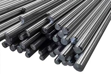
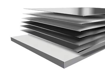
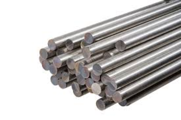
Grade 5 Ti-6Al-4V Titanium Plates & Bars feature a two-phase microstructure combining HCP alpha and body-centered cubic (BCC) beta phases, stabilized by 6% aluminum and 4% vanadium respectively.
Vanadium segregates preferentially into the beta phase, creating microscopic zones of lower electrical resistivity. This dual-phase conductivity causes the oxide layer to grow at different rates across grain boundaries, muting higher-order tones like green and pink into darker, bronze-tinted variations.
Engineering Rule of Thumb: Based on our CNC production data, Ti-6Al-4V components require 3 to 7 Volts higher potential than CP Grade 2 to achieve the identical optical wavelength interference band.
Industrial Equipment Setup & Electrolyte Chemistry Selection
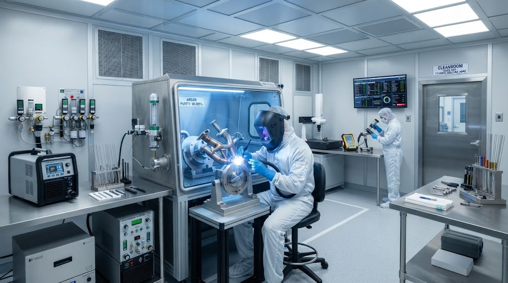
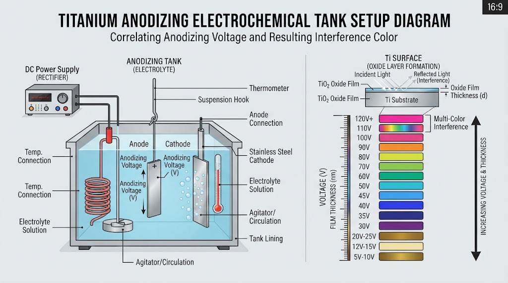
Industrial titanium anodizing requires stable DC rectification, inert tank linings, and precise electrolyte formulation to prevent localized surface pitting.
1. DC Power Supply Rectification
Select a switch-mode or linear DC power supply capable of 0–120V output and 0–15A continuous current per square foot of workpiece surface area. Voltage ripple must remain under 1.5% RMS. Excessive AC ripple induces dielectric breakdown, causing hazy or burnt films.
2. Tank Architecture and Cathode Materials
Use chemical-resistant polypropylene, PVDF, or high-density polyethylene (HDPE) processing tanks. Cathodes should consist of commercially pure Grade 1/2 titanium sheet or high-grade 316L stainless steel.
Maintain a cathode-to-anode surface area ratio of at least 2:1 to 3:1. Keep cathodes positioned symmetrically on both sides of the tank to ensure uniform current distribution across complex geometries.
3. Electrolyte Chemistry Formulations
Trisodium Phosphate (TSP) Solution: 3% to 5% by weight (30–50 g/L in deionized water). This is the industrial standard for color-coded medical instruments, yielding clean optical interference with broad voltage stability.
Ammonium Sulfate / Borax: 40 g/L (NH₄)₂SO₄ combined with 10 g/L sodium tetraborate. Offers high electrical conductivity and stable bath temperatures during continuous batch production.
Dilute Phosphoric Acid (H₃PO₄): 5% to 8% volumetric concentration. Primarily used for specialized architectural finishing and preparatory stages for structural bonding.
The China Titanium 5-Stage Industrial Anodizing Protocol
To eliminate color variation and optimize coating adhesion on complex Titanium CNC Machining Services components, China Titanium Factory adheres to a strict 5-stage protocol.
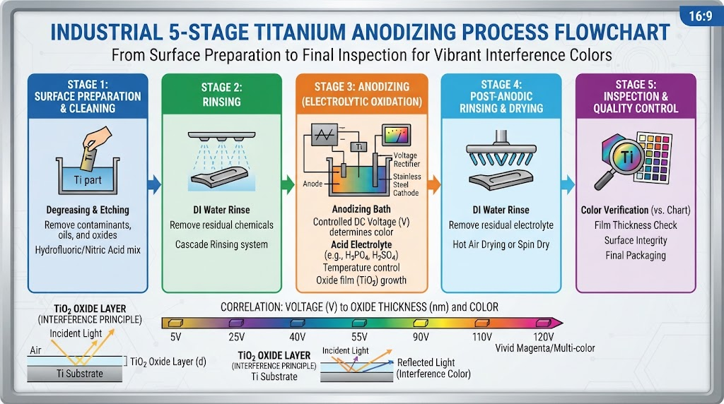
Stage 1: Alkaline Degreasing & Ultrasonic Cavitation
Machining lubricants and oils leave hydrophobic organic films on raw metal surfaces. Workpieces undergo ultrasonic degreasing in a non-silicated, mildly alkaline bath (pH 9.5–11.0) heated to 55°C (131°F) for 8 to 12 minutes, followed by a high-pressure cascade rinse.
Stage 2: Micro-Etching & ASTM F86 Surface Preparation
Titanium instantly develops an irregular, native passivated oxide (1.5–5 nm) when exposed to air. To establish a clean, reactive substrate for fresh barrier growth, parts are micro-etched using a controlled ammonium bifluoride solution (or dilute Multi-Etch) for 15–45 seconds.
Medical implant components are pre-passivated in strict accordance with ASTM F86 via nitric acid immersion (20–40 vol% HNO₃ at 50°C) to dissolve any iron smear contamination introduced during CNC tooling contact.
Stage 3: Pure Titanium Racking and Fixturing
All contact tooling, hanging hooks, and spring racks must be fabricated from Grade 1 or Grade 2 Commercially Pure Titanium. Aluminum, copper, or steel fixtures will dissolve electrochemically, contaminate the bath, or siphon current from the titanium components.
Racking contacts must exert sufficient mechanical spring pressure to overcome contact resistance, placed strategically on non-critical functional surfaces.
Stage 4: Controlled Voltage Ramping & Current Stabilization
Submerge the racked parts completely into the electrolyte solution with the power supply set to low initial potential. Ramp the voltage upward at a steady rate of 1.5 to 2.0 Volts per second until the target potential is reached.
Maintain the target voltage for 20 to 45 seconds. During this hold time, the dielectric barrier layer grows and electrical resistance spikes, causing the measured current density to decay exponentially toward zero. Once current draw plateaus below 0.05 A/dm², the oxide layer has reached equilibrium thickness.
Stage 5: High-Purity DI Water Rinsing & Controlled Air Drying
Immediately remove the components from the bath and transfer them through a three-stage counter-flow cascade rinse using deionized (DI) water with electrical conductivity maintained below 10 µS/cm. Blow dry using filtered, oil-free compressed nitrogen or clean air at 60°C to prevent mineral deposits.
Industrial Specifications: AMS 2488 Type II vs. Type III Color Anodization
Surface finishing standards in aerospace, defense, and medical sectors fall into two distinct engineering classifications.
AMS 2488 Type II: Anti-Galling Wear Resistance
Published by SAE International, AMS 2488 Type II defines a non-decorative, heavy conversion coating produced in high-pH alkaline electrolytes (typically NaOH or KOH solutions at pH 12–14).
Unlike thin optical interference films, Type II anodization creates a dark grey or charcoal microcrystalline oxide layer 2 to 5 microns thick. This coating eliminates the severe galling, fretting, and seizing tendencies of Titanium Fasteners & Surface Treatments in sliding aerospace assemblies.
Type III: Thin-Film Color Anodization
Type III anodizing produces the optical interference barrier layers detailed in this guide. Its primary industrial applications include color-coding orthopedic bone plates and screws for surgical identification, facilitating fast sorting in surgical theaters, and protecting implant surfaces in compliant Medical Grade Titanium Materials.
Engineering Troubleshooting Matrix: Resolving Common Defects
When running high-volume anodizing lines, electrochemical shifts or surface contamination can cause parts to fall out of spec. Use this matrix to identify root causes and implement corrective actions.
| Observed Defect | Root Cause Mechanism | Immediate Corrective Action |
|---|---|---|
| Patchy, Blotchy Color Distribution | Residual machining oils or uneven native oxide thickness prior to immersion. | Increase ultrasonic degrease time; verify etching step using a complete water-break-free test. |
| Localized Arc Burning & Pitting | Loose contact fixturing, excessive voltage ramp speed, or chloride contamination (>50 ppm). | Tighten CP-Ti spring racks; ramp voltage at ≤2 V/s; dump and remake bath with <10 µS/cm DI water. |
| Dull, Washed-Out Hue | Surface roughness too high (Ra > 1.2 µm) causing non-specular diffuse light scattering. | Electropolish, micro-hone, or mechanically buff parts to Ra ≤ 0.4 µm prior to anodizing. |
| Color Shift Across Single Batch | Voltage drop across undersized busbars or insufficient cathode-to-anode distance. | Increase cross-sectional area of titanium carrier racks; space workpieces ≥ 50 mm apart. |
China Titanium Factory: Precision Anodized Components & Material Solutions
China Titanium Factory operates dedicated manufacturing lines providing full-spectrum titanium supply, multi-axis CNC machining, and specialized surface treatments. We support aerospace contractors, medical device manufacturers, and high-performance industrial engineering projects globally.
Every lot undergoes rigorous surface analysis and is accompanied by certified Material Test Reports (MTR) meeting ASTM B348, AMS 4928, and ISO 13485 standards.
Need Precision Anodized Titanium Components?
From stock titanium raw materials to fully machined and anodized medical or aerospace assemblies, China Titanium Factory delivers certified metallurgical precision.
Request an Engineering QuoteFrequently Asked Questions (FAQ)
How durable is titanium color anodizing under continuous wear?
Because Type III color anodizing is an ultra-thin barrier layer (20 to 250 nanometers), abrasive sliding contact will eventually wear away the film and expose the grey metal underneath. However, for non-sliding parts or recessed surfaces, the chemically inert TiO₂ film will not fade, chip, flake, or peel over decades of atmospheric or fluid exposure.
Is color-anodized titanium biocompatible for surgical implants?
Yes. Titanium anodizing uses no dyes, heavy metal pigments, or hazardous binding agents. The resulting oxide layer is pure titanium dioxide, the same compound that gives raw titanium its natural biocompatibility and corrosion resistance. Anodization meets the biological safety requirements of ISO 10993 and ASTM F86.
Can you strip and re-anodize a titanium component?
Yes. You can strip an existing anodic oxide layer using an ammonium bifluoride solution or light mechanical polishing. Because the oxide layer is less than a micron thick, stripping it removes a negligible amount of base metal, allowing precision-machined tolerances to remain intact.
Does titanium anodizing affect electrical conductivity?
Yes. The titanium dioxide film functions as a dielectric insulator. As the anodizing voltage increases and creates a thicker oxide layer, surface contact electrical resistance rises accordingly. For applications requiring low electrical contact resistance, critical areas should be masked prior to processing.