





















Fundamentals of the Galvanic Series: Thermodynamics, Driving Voltage, and Polarization
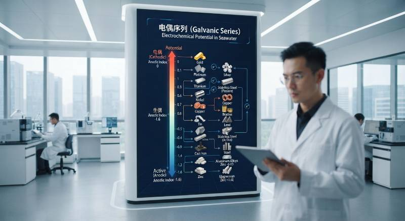
The electrochemical series defines the thermodynamic tendency of metals to donate electrons, providing the theoretical foundation for sacrificial anode cathodic protection (SACP) and impressed current cathodic protection (ICCP). By coupling a more electronegative base metal to carbon steel, corrosion is redirected entirely to the sacrificial element to preserve the protected cathode. In natural electrolytes like seawater or soil, kinetic parameters dictate the practical operating potential rather than standard reduction states alone.
The Standard Hydrogen Electrode (SHE) scale sets the baseline reduction potentials under ideal molar activities at 25°C. Practical cathodic protection relies instead on the practical galvanic series measured against reference half-cells such as Copper/Copper Sulfate (CSE) for soil or Silver/Silver Chloride (Ag/AgCl) for marine environments.
The operational driving voltage (ΔE) controls the rate of protective current discharge from the anode to the steel structure:
Driving Voltage Formula: ΔE = |Eanode, closed-circuit - Ecathode, polarized|
According to mixed-potential theory, when an anode couples to steel, both electrodes polarize away from their open-circuit potentials (Eocp) to reach a common mixed potential (Ecorr, coupled). To prevent corrosion per AMPP / NACE SP0169 standards, the steel must polarize to a minimum protective threshold of -0.850 V vs. CSE (-0.800 V vs. Ag/AgCl) under aerobic conditions, or -0.950 V vs. CSE in anaerobic, sulfate-reducing bacteria (SRB) environments.
Driving voltage must be carefully optimized. Insufficient driving voltage fails to fully polarize the structure, leaving unprotected corrosion pits. Excessive driving voltage causes cathodic overprotection, inducing atomic hydrogen charging on high-strength steels and triggering catastrophic hydrogen embrittlement.
Sacrificial Anode Materials: Electrochemical Metrics and Metallurgical Benchmarks
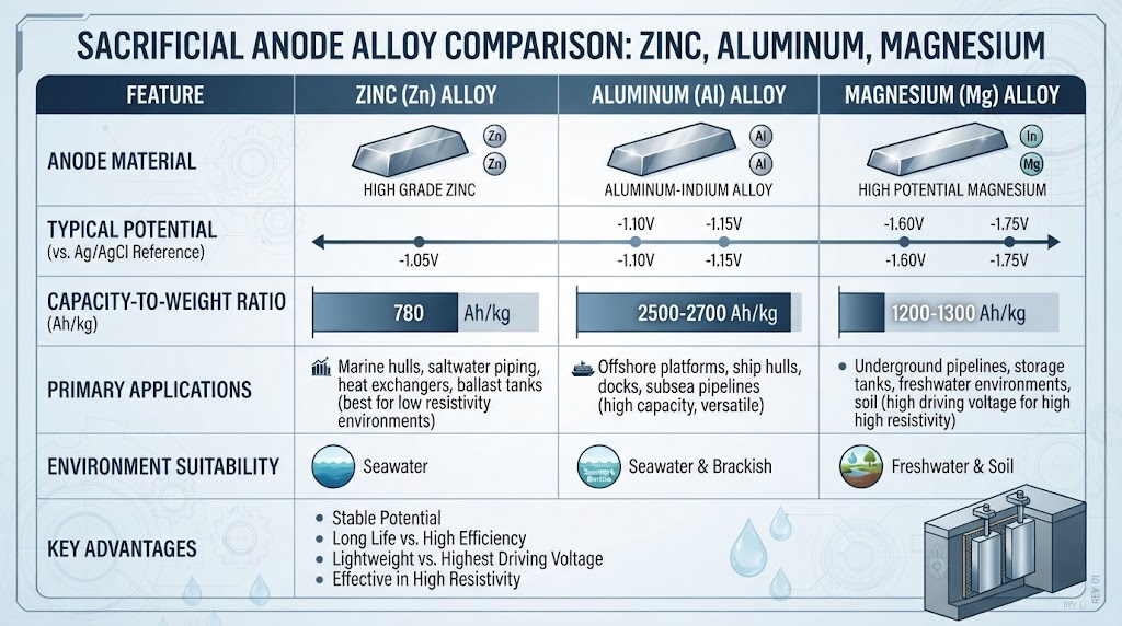
Galvanic cathodic protection deploys three primary alloy chemistries: Zinc, Aluminum-Zinc-Indium, and Magnesium. Selecting the proper alloy requires balancing closed-circuit potential, electrochemical capacity, and bulk consumption rates.
| Alloy Type | Standard Specification | Closed-Circuit Potential (V vs Ag/AgCl) | Theoretical Capacity (Ah/kg) | Practical Capacity (Ah/kg) | Current Efficiency (%) | Consumption Rate (kg/A·yr) |
|---|---|---|---|---|---|---|
| High-Purity Zinc (Type II) | ASTM B418 / MIL-A-18001K | -1.03 | 820 | 780 | 95 | 11.2 |
| Aluminum-Zinc-Indium | DNV-RP-B401 / MIL-A-24779 | -1.05 to -1.10 | 2,980 | 2,300–2,600 | 85–90 | 3.4 |
| High-Potential Magnesium | ASTM B843 Grade M1C | -1.70 to -1.75 (vs CSE) | 2,200 | 1,100–1,230 | 50–55 | 7.1–8.0 |
| Standard Magnesium (AZ63) | ASTM B843 Grade AZ63B | -1.50 to -1.55 (vs CSE) | 2,200 | 1,000–1,100 | 45–50 | 8.0–8.8 |
Zinc systems offer high current efficiency (95%) and operate reliably in marine sediments and ambient seawater. However, Zinc's high density (7.14 g/cm3) and low practical capacity (780 Ah/kg) impose heavy weight penalties on offshore jacket structures.
Aluminum alloys activated with indium provide nearly triple the practical capacity of zinc (2,500 Ah/kg) at roughly one-third the mass density (2.70 g/cm3). This efficiency makes aluminum the industry standard for marine platforms and subsea pipelines compliant with ASTM International guidelines.
Magnesium yields the highest driving voltage (-1.75 V vs. CSE), making it effective in high-resistivity onshore soils. The trade-off is low current efficiency (50%) caused by parasitic micro-galvanic self-corrosion and local hydrogen evolution.
Electrolyte Resistivity Boundaries and Anode Passivation Mechanisms
Electrolyte resistivity (ρ) dictates the current output of galvanic anodes. As resistivity increases from open seawater (20–30 Ω·cm) to estuarine brackish water (100–500 Ω·cm) and dry soils (>5,000 Ω·cm), galvanic anodes face severe ohmic limitations.
Beyond current attenuation, sacrificial anodes are vulnerable to chemical passivation:
High-Temperature Zinc Polarity Reversal: In potable water or geothermal heat exchangers exceeding 60°C (140°F), zinc's corrosion product transitions from porous, conductive Zn(OH)2 to dense, compact zinc oxide (ZnO). This shift raises the zinc's electrochemical potential to approximately -0.55 V vs. CSE. Consequently, the zinc becomes cathodic to structural steel, accelerating catastrophic perforation of the steel vessel.
Aluminum Silting and Calcification: In anaerobic seabed muds or warm carbonate-rich waters, aluminum anodes can develop high-resistance surface films of alumina hydrate (Al2O3·3H2O) and dense CaCO3 scales, choking off current output.
Magnesium Efficiency Collapse: In low-resistivity saline waters, magnesium undergoes intense parasitic self-corrosion. Current efficiency drops below 30%, rapidly exhausting the anode without providing proportional cathodic protection to the cathode.
Sacrificial Anodes vs. Dimensionally Stable MMO Titanium ICCP Anodes
To overcome the mass and resistivity limits of sacrificial systems, modern infrastructure relies on Impressed Current Cathodic Protection (ICCP) using Mixed Metal Oxide (MMO) coated titanium anodes.
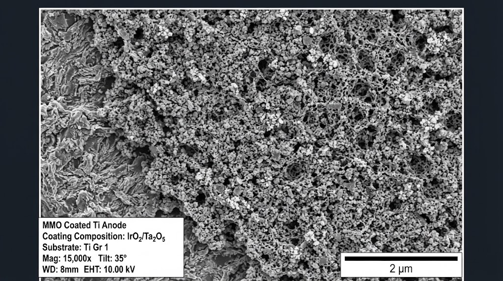
To systematically evaluate the transition from sacrificial systems to ICCP, we developed the 3-Vector Cathodic Viability Framework (3V-CVF):
Electrolyte Resistivity Gradient (ρ): Sacrificial anodes work best where ρ < 500 Ω·cm. For environments where ρ exceeds 1,000 Ω·cm, the driving voltage of galvanic anodes cannot deliver adequate current density without impractically tight anode spacing. ICCP systems adjust driving voltages from 10 V to 50 V or higher, enabling uniform current throw across complex structures.
Mass-to-Life Consumption Vector (Km): Sacrificial alloys consume mass at high rates (3.4 to 11.2 kg/A·yr). MMO titanium substrates exhibit near-zero consumption (<1.0 to 2.0 mg/A·yr). This cuts installed anode weight by more than 85%, eliminating structural drag and deck deadweight on offshore platforms.
Substrate Dielectric Stability (Ecrit): ASTM B265 Grade 1 titanium substrates form a tenacious, self-healing dielectric TiO2 passive film. In chloride-rich media, this film maintains dielectric integrity up to a critical breakdown potential of Ecrit = 10–12 V (and over 50 V in sulfate environments), ensuring that current discharges entirely through the catalytic electrocatalyst layer.
China Titanium Factory manufactures dimensionally stable MMO anodes using an electrochemically sintered IrO2/Ta2O5 or RuO2/TiO2 crystalline matrix on pure Grade 1 titanium. Explore our precision engineered solutions across the China Titanium Factory Products catalog for marine, energy, and civil infrastructure applications.
| Evaluation Parameter | Sacrificial Anodes (Al/Zn) | MMO Coated Titanium (Grade 1 Substrate) |
|---|---|---|
| Electrochemical Mechanism | Galvanic dissolution of substrate alloy | Electrocatalytic evolution of O2 / Cl2 |
| Consumption Rate | 3.40 to 11.20 kg/A·yr | 0.5 to 2.0 mg/A·yr (negligible mass loss) |
| Driving Voltage Control | Fixed by thermodynamics (0.25 to 0.45 V) | Dynamically regulated via TRU (0 to 50+ V) |
| Hydrodynamic Drag / Mass Penalty | Severe (requires metric tons of alloy) | Minimal (>85% weight reduction) |
| High-Temperature Performance (>60°C) | High passivation and polarity reversal risk | Stable up to 90°C+ with Ta2O5 intermediate |
Extreme Niche Applications: Where Traditional Sacrificial Anodes Fail
Certain operating environments render sacrificial alloys completely unviable:
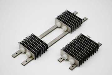
High-Resistivity Soil & Concrete (>10,000 Ω·cm): Galvanic anodes cannot overcome the high internal resistance of reinforced concrete. MMO titanium ribbon mesh and expanded mesh ribbons cast directly into concrete bridges, parking decks, and marine pilings provide uniform cathodic protection for over 75 years without spalling.
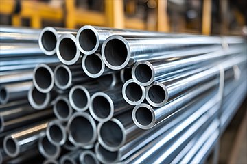
Deep-Well Groundbeds & Geothermal Brines (>60°C): Deep aquifers and high-temperature downhole installations cause rapid consumption or thermal passivating scale on zinc and magnesium. MMO tubular titanium strings with mixed tantalum-iridium oxide coatings withstand acidic environments and high temperatures up to 90°C.
Offshore Wind Monopiles (25–30 Year Design Life): Massive offshore foundations require high current outputs to polarize internal and external submerged zones. Sacrificial blocks require costly subsea replacement campaigns. MMO probe and disk anodes mounted flush in Grade 2 titanium holders deliver continuous, monitored protection across the entire asset design life.
Cathodic Protection Sizing Calculations and Design Formulas
Cathodic protection design balances current demand, electrolyte resistivity, circuit resistance, and design life per standards such as DNV-RP-B401 and AMPP/NACE SP0100.
1. Total Cathodic Current Demand:
Itotal = Ac · fc · icm
Where Ac is the total surface area of the steel structure (m2), fc is the coating breakdown factor (dimensionless, increasing over time), and icm is the design current density demand (A/m2).
2. Anode Mass Sizing (Sacrificial Anodes):
M = (Imean · t · 8760) / (u · ε)
Where M is the total anode mass (kg), Imean is mean design current (A), t is design life (years), 8760 is hours per year, u is the anode utilization factor (typically 0.80 to 0.90), and ε is the practical electrochemical capacity (Ah/kg).
3. Anode Ground Resistance (Dwight and McCoy Equations):
For an isolated slender cylindrical or tubular anode suspended in a uniform electrolyte, anode resistance Ra (Ω) is calculated using the modified Dwight formula:
Ra = (ρ / (2 · π · L)) · [ln(4 · L / r) - 1]
Where ρ is electrolyte resistivity (Ω·m), L is active anode length (m), and r is anode radius (m).
For flush-mounted plate or disk anodes, McCoy's empirical formula is applied:
Ra = 0.315 · ρ / √(A)
Where A is the exposed surface area of the anode plate (m2).
The China Titanium Factory Anode Life-Cycle & Integrity Protocol
To eliminate early failures in extreme environments, our metallurgical team developed the 4-Stage Oxide Sintering & Substrate Verification Protocol:
Precision Substrate Preparation: Grade 1 titanium substrates complying with ASTM B265/B338/B348 undergo grit blasting with pure white corundum (surface profile Ra 2.5–4.0 μm), followed by boiling oxalic acid etching to create a uniform, interlocking hydride surface layer.
Multi-Layer Thermal Decomposition Sintering: Liquid solutions containing stoichiometric ratios of iridium tetrachloride (IrCl4), tantalum pentachloride (TaCl5), or ruthenium precursors are robotically applied and calcined across 18 to 26 thermal cycles at 450°C–520°C to build a durable rutile solid-solution crystal matrix.
Dielectric Quality & Thickness Verification: 100% of finished anode surfaces undergo non-destructive X-ray Fluorescence (XRF) testing to verify catalyst loading (minimum 10–20 g/m2) and high-voltage spark testing to confirm zero micro-porosity through the titanium substrate.
Accelerated Life Testing: Production batches are subjected to accelerated life testing per NACE TM0108 / NACE TM0294 in 1.0 M H2SO4 at extreme current densities of 10,000 A/m2, ensuring an operational lifetime exceeding 50 years under standard CP current ratings.
Standardized Technical Specifications & Quality Certifications
China Titanium Factory manufactures all CP substrates and MMO components under strict ISO 9001:2015 and AS9100D aerospace quality frameworks.
| Element / Property | ASTM B265 Grade 1 (Standard Substrate) | ASTM B265 Grade 2 (Structural Substrate) |
|---|---|---|
| Titanium (Ti) | ≥ 99.5% (Balance) | ≥ 99.2% (Balance) |
| Iron (Fe) | ≤ 0.20% | ≤ 0.30% |
| Oxygen (O) | ≤ 0.18% | ≤ 0.25% |
| Carbon (C) | ≤ 0.08% | ≤ 0.08% |
| Tensile Strength (min) | 240 MPa (35 ksi) | 345 MPa (50 ksi) |
| Yield Strength (0.2% offset) | 170–310 MPa | 275–450 MPa |
| Elongation in 2 in. (min) | 24% | 20% |
Every shipment is accompanied by fully traceable EN 10204 3.1 Material Test Certificates (MTC) documenting chemical analysis, mechanical property verification, noble metal loading levels, and accelerated service life test data.
Frequently Asked Questions: Cathodic Protection & Anode Selection
How do 25-year lifecycle costs compare between sacrificial anodes and MMO titanium ICCP systems?
Sacrificial systems have lower upfront equipment costs but require massive material volume and frequent subsea or excavation changeouts. For example, a 50-Amp continuous current demand over 25 years requires over 4,250 kg of aluminum alloy. An equivalent MMO titanium ICCP system requires less than 45 kg of titanium substrate. Factoring in vessel day rates, diver operations, structural deadweight, and replacement cycles, MMO titanium ICCP reduces total cost of ownership (TCO) by 38% to 62% on long-term assets.
How do you verify genuine MMO coating quality and prevent premature failure?
China Titanium Factory validates anode integrity through four rigorous steps: 1) Verifying raw substrate chemistry via EN 10204 3.1 MTCs for ASTM B265 Grade 1 titanium; 2) Measuring coating mass density (g/m2) via calibrated XRF spectrometry; 3) Performing thermal shock testing by heating samples to 450°C followed by immediate water quenching to verify coating adhesion; and 4) Conducting accelerated life testing per NACE TM0108 in 1 M sulfuric acid.
Why is zinc prohibited in high-temperature water heaters and geothermal heat exchangers?
At temperatures exceeding 60°C (140°F), zinc undergoes polarity reversal. Its corrosion film shifts from conductive zinc hydroxide to a dense zinc oxide layer. This increases zinc's operating potential to roughly -0.55 V vs. CSE, making it cathodic relative to carbon steel and accelerating structural corrosion. In elevated temperature systems, MMO titanium or high-silicon cast iron ICCP systems must be specified.
Can depleted sacrificial anode systems on aging offshore assets be retrofitted with MMO ICCP?
Yes. Retrofitting aging platforms with new sacrificial anode brackets requires costly underwater welding and introduces significant weight penalties. In contrast, installing MMO titanium probe anodes or suspended string tension anodes powered by deck-mounted Transformer Rectifier Units (TRUs) delivers targeted, adjustable cathodic protection without significant structural additions.
Engineering CP Solutions: 3-Step Implementation Pathway
Direct Engineering to Production Pathway
Transition from electrochemical sizing calculations to verified, factory-direct manufacturing:
Step 1: Submit Operating Parameters & Requirements: Provide electrolyte resistivity, environmental operating temperatures, total current demand, design life requirements, and structural CAD drawings.
Step 2: Engineering Evaluation & Custom Sizing: Receive a comprehensive technical review within 24 hours, including substrate sizing calculations, MMO coating formula selection (IrO2/Ta2O5 or RuO2/TiO2), DFM drawings, and transparent pricing.
Step 3: Direct Metallurgical Consultation & Certified Production: Review specifications with our Senior Cathodic Protection Metallurgist, approve production prototypes with complete EN 10204 3.1 MTCs, and initiate rapid manufacturing.