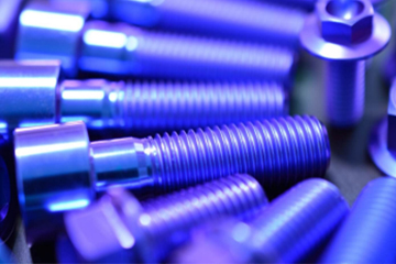
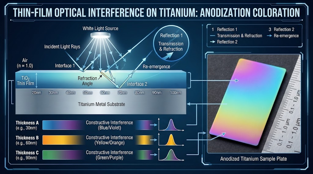
Titanium anodizing produces color through thin-film optical interference rather than dyes or pigments. Applying a controlled direct current (DC) voltage in an electrolytic bath forces oxygen ions to migrate into the titanium surface, growing an amorphous barrier layer of transparent Titanium Dioxide (TiO2) at a precise rate of 1.6 to 2.0 nanometers per volt (nm/V).
The perceived color is governed by specular reflection at two distinct phase boundaries: the outer air-to-oxide boundary ($R_1$) and the inner oxide-to-metal interface ($R_2$). When incident white light strikes the anodized surface, a portion of the light wave reflects immediately off the transparent oxide film with a $180^\circ$ ($\pi$-radian) phase shift due to the higher refractive index of TiO2 ($n \approx 2.50\text{–}2.65$) relative to air ($n \approx 1.00$).
The remaining fraction of the light wave enters the oxide layer, travels through its nanometer-scale thickness ($d$), reflects off the metallic titanium substrate ($R_2$), and emerges back into the environment. The mathematical condition for constructive optical wave interference is defined by the classical thin-film equation:
Constructive Interference Formulation:
$2 n d \cos(\theta_t) = \left(m - \frac{1}{2}\right) \lambda$
Where $n$ is the refractive index of amorphous TiO2 ($\approx 2.55$), $d$ is the barrier oxide film thickness (nm), $\theta_t$ is the angle of refraction inside the film, $m$ is the spectral order of interference ($m = 1, 2, 3\dots$), and $\lambda$ is the reinforced visible wavelength.
Because the oxide thickness $d$ is directly proportional to the applied forming voltage ($d = k \cdot V$, where $k$ is the electrochemical formation constant), varying the voltage precisely modulates the reinforced wavelength $\lambda$ across the visible electromagnetic spectrum (380 nm to 750 nm).
A fundamental physical limitation of Type III thin-film color anodizing is the inability to produce pure, saturated primary red or deep jet black.
Producing true primary red requires constructive interference isolated near 650–700 nm without overlapping harmonic reinforcement in the lower blue-green spectrum. As the oxide layer thickens toward higher voltages ($>75\text{V}$), second-order ($m=2$) interference bands simultaneously amplify shorter wavelengths (violet and blue at 400–450 nm), blending the perceived color into magenta, rose-pink, or reddish-purple rather than spectral red.
True black requires total absorption or destructive cancellation of all wavelengths across the entire visible spectrum (400–700 nm). Because thin-film titanium dioxide is chemically transparent and non-absorptive, constructive reflection of at least one spectral band always occurs. Achieving a genuine matte or semi-gloss black finish requires Plasma Electrolytic Oxidation (PEO/MAO) to develop thick, micro-porous ceramic coatings, or Physical Vapor Deposition (PVD) applying titanium carbonitride (TiCN) or diamond-like carbon (DLC) layers.
The electrochemical anodization of titanium exhibits distinct color orders. First-order interference occurs at lower oxide thicknesses (12V to 60V), producing broad, subtle shades. Second-order interference occurs at elevated voltages (65V to 110V+), where sharper phase differences produce vibrant, saturated tones.
The following empirical matrix reflects calibrated production runs conducted under controlled laboratory conditions ($10\text{ wt}\%\ \text{H}_3\text{PO}_4$ electrolyte at $21^\circ\text{C} \pm 1^\circ\text{C}$):
| Applied Potential (V DC) | Oxide Thickness ($d$, nm) | CP Grade 2 Perceived Hue | Ti-6Al-4V Grade 5 Hue | Interference Order | Reinforced $\lambda$ (nm) |
|---|---|---|---|---|---|
| 0V – 5V | 5 – 10 nm | Natural Silver / Gray | Natural Matte Gray | Native Oxide | None (Sub-optical) |
| 12V – 14V | 22 – 26 nm | Pale Bronze / Straw Yellow | Faint Champagne | 1st Order | 390 – 420 nm |
| 18V – 22V | 34 – 42 nm | Dark Brown / Purple Violet | Deep Violet | 1st Order | 430 – 460 nm |
| 25V – 28V | 48 – 54 nm | Royal Blue / Navy Cobalt | Dark Cobalt Blue | 1st Order | 470 – 490 nm |
| 32V – 36V | 60 – 68 nm | Light Sky Blue / Cyan | Sky Blue | 1st Order | 500 – 530 nm |
| 45V – 50V | 85 – 95 nm | Champagne Gold / Canary | Warm Gold | 1st Order | 570 – 590 nm |
| 55V – 62V | 105 – 118 nm | Rose Gold / Salmon Pink | Rose Bronze | 1st Order | 610 – 640 nm |
| 68V – 74V | 130 – 142 nm | Vibrant Magenta / Violet Red | Deep Magenta | 2nd Order | 410 nm + 660 nm |
| 78V – 85V | 150 – 165 nm | Teal Blue / Turquoise | Cyan / Turquoise | 2nd Order | 490 – 510 nm |
| 90V – 100V | 175 – 195 nm | Emerald Green / Lime | Apple Green | 2nd Order | 520 – 550 nm |
| 105V – 115V+ | 205 – 225 nm | Pale Green / Mint / Pink Wash | Faint Greenish Pink | 3rd Order | Broad Spectrum Mix |
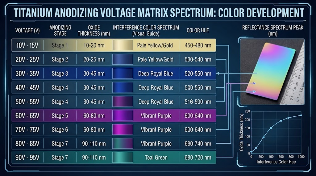
The low-voltage window forms the initial dielectric barrier oxide ($20\text{ nm} \le d \le 55\text{ nm}$). Current draw spikes instantly to peak density before decaying exponentially as dielectric resistance builds across the anode.
Achieving a saturated 25V–28V royal blue requires precise surface cleanliness. Trace hydrocarbons or unetched native oxides will skew the interference profile downward toward dull bronze or brownish-purple.
The mid-voltage band represents first-order interference across longer visible wavelengths. The 45V–50V threshold produces high-purity gold and canary yellow tones, which serve as visual identification standards in surgical instrumentation and orthopedics.
Thermal stability in the electrolyte bath is critical within this range. An electrolyte temperature deviation exceeding $\pm 2.5^\circ\text{C}$ shifts the target growth kinetics, altering a 58V rose-gold into a muddy 52V yellow.
Voltages exceeding 70V trigger second-order interference, producing saturated emerald greens, teals, and magentas. These higher potentials place extreme dielectric stress across the oxide barrier.
Exceeding the dielectric breakdown threshold of the bath chemistry initiates local micro-arcing (dielectric puncture). This burns the substrate, creating powdery, non-adherent white spots of rutile TiO2.
A frequent error in industrial titanium finishing is applying identical voltage settings across different metallurgical grades. Titanium alloys do not exhibit identical electrochemical growth constants.
Commercially Pure (CP) titanium grades (such as ASTM B265 Grade 2, UNS R50400) possess an alpha single-phase crystal structure with minimal alloying elements ($>99\text{ wt}\%\ \text{Ti}$). CP titanium establishes a uniform barrier film at a constant rate of approximately $1.95\text{ nm/V}$.
Metallurgical Engineering Insight:
Grade 5 Ti-6Al-4V (ASTM F136 / ASTM B348, UNS R56400) is a dual-phase $\alpha+\beta$ alloy containing nominally 6% Aluminum ($\alpha$-stabilizer) and 4% Vanadium ($\beta$-stabilizer). Vanadium segregates preferentially along beta grain boundaries, creating microscopic regions of lower electrical resistivity and localized dielectric leakage.
Consequently, Ti-6Al-4V requires an empirical offset of +3V to +8V higher potential than Grade 2 to achieve identical optical film thicknesses and matching color hues. Aluminum also integrates into the oxide film as $Al_2O_3$, slightly altering the refractive index $n$ and shifting the perceived interference spectrum toward cooler hues.
| Target Perceived Color | CP Grade 2 Set Voltage (V DC) | Ti-6Al-4V Grade 5 Set Voltage (V DC) | Required Calibration Offset |
|---|---|---|---|
| Deep Royal Blue | 25.0 V | 29.5 V | +4.5 V |
| Sky Cyan Blue | 34.0 V | 39.0 V | +5.0 V |
| Champagne Gold | 48.0 V | 54.0 V | +6.0 V |
| Rose Pink | 58.0 V | 64.5 V | +6.5 V |
| Emerald Green | 92.0 V | 99.5 V | +7.5 V |
In aerospace and defense engineering, anodized titanium must conform to stringent SAE Aerospace Material Specifications. Confusing AMS 2488 Type II with Type III color anodizing can lead to non-conformance and critical component rejection.
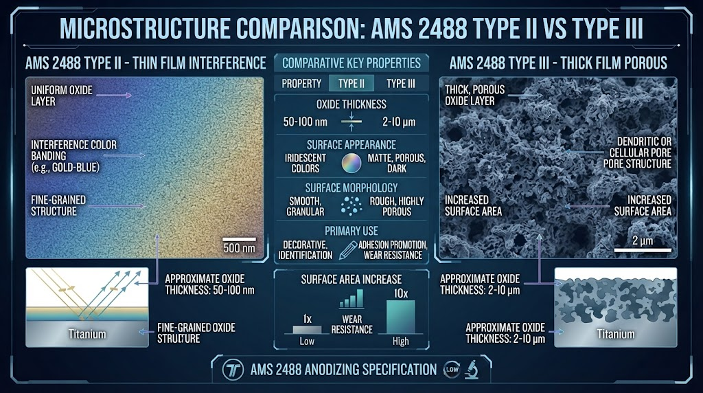
The aerospace standard SAE AMS 2488 classifies titanium surface treatments into distinct functional categories:
| Property / Metric | AMS 2488 Type II (Wear / Anti-Galling) | AMS 2488 Type III / Commercial Color |
|---|---|---|
| Primary Engineering Intent | Anti-galling, wear resistance, solid lubricant retention | Color identification, passivation, aesthetic coding |
| Electrolyte Chemistry | Strong Alkaline ($\text{NaOH} / \text{KOH}$, $\text{pH} > 12$) | Acidic / Neutral ($\text{H}_3\text{PO}_4$, $\text{TSP}$, $\text{pH } 1.5\text{–}7.0$) |
| Layer Morphology | Micro-porous conversion layer ($2\text{–}6\ \mu\text{m}$) | Dense, non-porous barrier film ($20\text{–}250\text{ nm}$) |
| Visual Appearance | Uniform Matte Gray to Charcoal / Olive Drab | Multi-spectrum interference colors (Blue, Gold, Green) |
| Dimensional Growth | Measurable build-up: $1.5\ \mu\text{m} \pm 0.8\ \mu\text{m}$ | Negligible build-up: $< 0.25\ \mu\text{m}$ (Zero dimensional shift) |
| Fatigue Strength Impact | May reduce high-cycle fatigue by 10%–20% | Zero measurable impact on high-cycle fatigue life |
Bath chemistry dictates conductivity, breakdown voltage thresholds, and the clarity of the resulting color interference. Industrial production uses three primary electrolyte formulations:
Phosphoric Acid ($\text{H}_3\text{PO}_4$, 5% to 15% wt/vol): The standard for aerospace and industrial hardware. Phosphoric acid offers an expansive dielectric breakdown window ($>120\text{V}$), producing vibrant high-voltage greens and magentas without premature micro-pitting.
Trisodium Phosphate ($\text{Na}_3\text{PO}_4$ / TSP, 3% to 8% wt/vol): Preferred for medical implants and surgical tools. TSP is mildly alkaline to neutral ($\text{pH } 9\text{–}11$), non-toxic, easily rinsed, and delivers saturated first-order blues and golds.
Sulfuric Acid ($\text{H}_2\text{SO}_4$, 3% to 5% vol/vol): Highly conductive with high current efficiency, but has a low dielectric breakdown threshold ($\approx 45\text{V}$). It is largely limited to low-voltage bronze and blue applications.
Cell architecture requires careful attention to cathode selection and area ratios. While 316L stainless steel cathodes are common, grade-matched Titanium Mesh (Grade 1 or Grade 2) prevents iron-ion contamination in acidic baths. Iron leaching from stainless cathodes can co-deposit onto the titanium anode, causing hazy, cloudy color bands.
The cathode-to-anode surface area ratio must be maintained at a minimum of 2:1 or 3:1. A larger cathode surface prevents current-density bottlenecking and maintains a laminar electric field distribution across complex CNC geometries.
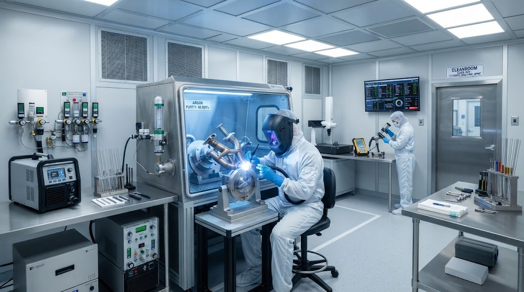
In our high-precision fabrication facilities, we apply a standardized 5-stage anodizing standard developed for tight-tolerance aerospace and medical components: the China Titanium Precision Voltage Matrix (CT-PVM) Protocol.
Substrate Profiling & Ultrasonic Degreasing: CNC machined parts undergo ultrasonic cleaning in an alkaline bath at $55^\circ\text{C}$ for 10 minutes to clear cutting fluid emulsions, followed by a double deionized (DI) water immersion rinse.
Micro-Etch Activation: Components are briefly immersed for 15–30 seconds in a calibrated acid pickle ($3\%\ \text{HF} + 20\%\ \text{HNO}_3$ balance $\text{H}_2\text{O}$) to remove the uneven native passive layer and micro-burrs, producing an active, chemically uniform baseline surface.
Constant-Current Voltage Ramping: Parts are racked using rigid titanium spring contacts and submerged in a temperature-controlled bath ($20^\circ\text{C} \pm 0.5^\circ\text{C}$). Power is delivered using a programmable DC power supply ramping at $1.5\text{ V/s}$ under constant current density ($1.5\text{ A/dm}^2$) until target voltage is reached, then held for 20 seconds.
Cascade DI Counterflow Rinsing: Substrates pass through a 3-stage cascade counterflow rinse tank maintaining water conductivity below $5\ \mu\text{S/cm}$ to stop all surface reactions instantly and prevent electrolyte drag-out staining.
Spectrophotometric CIE $L^a^b^$ Verification: Finished parts are dried with filtered nitrogen ($99.99\%$) and inspected using an industrial spectrophotometer to verify color coordinates against engineering tolerance limits ($\Delta E^ < 1.2$).
Pre-anodize mechanical surface preparation dictates the optical reflectivity of the finished part. A mirror-polished surface ($R_a < 0.1\ \mu\text{m}$) yields brilliant, highly reflective candy-like finishes, whereas a glass-bead blasted substrate ($R_a \approx 1.6\text{–}3.2\ \mu\text{m}$) diffuses light reflection, producing a matte pastel hue at identical voltages.
| Defect Symptom | Probable Root Cause | Corrective Engineering Action |
|---|---|---|
| Mottled, Blotchy Color Hue | Organic hydrocarbon residue or uneven native oxide film | Increase ultrasonic degrease time; apply fresh $\text{HF}/\text{HNO}_3$ pickle for 20s. |
| Localized Arc Burning / White Spots | Dielectric breakdown due to voltage spike or bath overheating ($>30^\circ\text{C}$) | Install bath chillers ($18\text{–}22^\circ\text{C}$); program linear voltage ramp ($< 2\text{ V/s}$). |
| Dull, Low-Chroma Pastel Color | High substrate surface roughness ($R_a > 2.0\ \mu\text{m}$) causing diffuse scatter | Mechanically polish or electropolish substrate to $R_a < 0.4\ \mu\text{m}$ prior to anodizing. |
| Color Fade After Finger Contact | Skin lipid deposition altering thin-film refractive index ($n_{oil} \approx 1.45$) | Clean with isopropanol (IPA); apply an ultra-thin hydrophobic sealant if required. |
Precision color anodizing is essential for identification, traceability, and safety compliance across mission-critical industries.
In medical manufacturing, ASTM F136 Grade 23 (Ti-6Al-4V ELI) orthopedic bone plates, spinal fixation rods, and cranial screws rely on color coding (e.g., Yellow = 2.0 mm diameter, Cyan = 2.5 mm, Magenta = 3.5 mm). This allows surgeons to rapidly identify matching drill bits and fasteners in the operating theater. Because Type III color anodization uses no organic dyes, it maintains full biocompatibility, passes ISO 10993 cytotoxicity testing, and withstands repeated autoclave sterilization cycles.
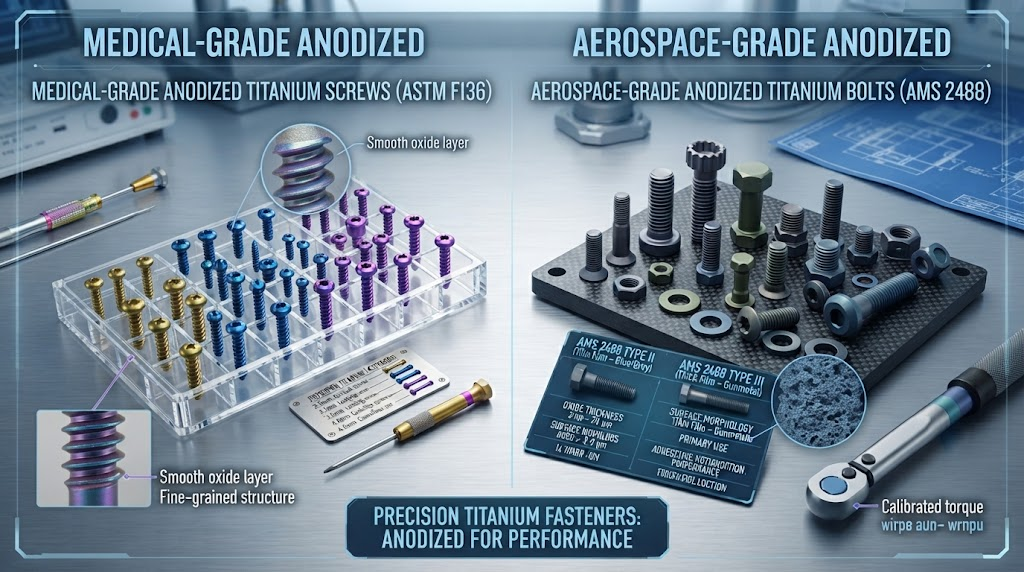
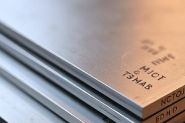
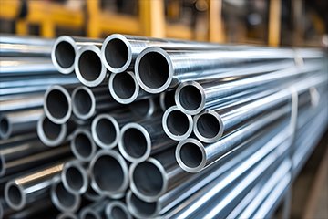
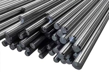
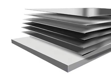
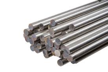
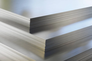
For aerospace fasteners and sub-assemblies, color anodizing provides instant visual sorting across metric and imperial thread pitches while enhancing atmospheric corrosion resistance. China Titanium Factory manufactures and delivers fully integrated titanium solutions, supplying raw mill products (plates, sheets, round bars, seamless tubes) and complex 5-axis CNC machined parts with high-precision, Nadcap-compliant surface finishing.
Yes. The titanium dioxide layer is chemically bonded and will not chip, peel, or flake like paint or electroplating. However, because the color film is only 20 to 250 nanometers thick, severe abrasive friction or strong reducing acids (such as hydrofluoric or concentrated hydrochloric acid) will physically wear away the oxide layer.
A continuous, ripple-filtered DC variable power supply rated for 0–120V and at least 5–10 Amps is recommended for industrial applications. Clean direct current with minimal AC ripple voltage ($< 1\%$) is critical to ensure uniform color formation and prevent localized micro-arcing at higher voltages.
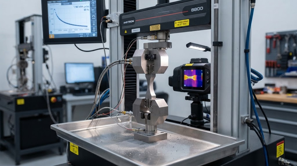
No. Type III color anodizing consumes less than 150 nm of base material and does not induce hydrogen embrittlement or reduce high-cycle fatigue strength. In contrast, heavy conversion processes like AMS 2488 Type II must be factored into fatigue life calculations during component structural design.
Yes, provided you are stepping upward in voltage. A part anodized at 25V (blue) can be re-submerged and anodized to 50V (gold) or 90V (green) without stripping. However, moving downward from green to blue requires completely stripping the existing oxide via chemical etching ($\text{HF}/\text{HNO}_3$) or mechanical polishing back to the bare titanium substrate.



Contact Us
Room 21003, 10th Floor, Unit 2, Building 1, Xianning International Plaza, No.29 Xianning West Road, Beilin District, Xi'an City
Copyright © Xi'an Shiguang Jingyan Technology Co., Ltd. All Rights Reserved.