





















Electrolyte Solutions for Titanium Anodizing: Bath Chemistry, AMS 2488 Type II vs. Type III Kinetics & Failure Modes
Titanium anodizing is an electrolytic conversion process engineered to produce functional oxide coatings ranging from thin-film optical interference layers (15 nm to 300 nm) to heavy, anti-galling dielectric conversion structures (1.0 μm to 2.5 μm). Unlike aluminum anodizing, which builds a thick, porous aluminum oxide (Al2O3) matrix that readily absorbs organic dyes, titanium anodizing is fundamentally non-porous and non-dyed in standard industrial configurations. Engineering compliance across aerospace and medical sectors demands strict adherence to governing specifications, primarily SAE AMS 2488F for heavy alkaline wear-resistant conversion and ASTM F86 alongside ISO 10993 for biocompatible optical color coding.
The mechanical, tribological, and optical properties of the resulting titanium dioxide (TiO2) film depend directly on the chosen electrolyte bath chemistry, applied potential (DC voltage), current density, bath temperature, and substrate metallurgy. While dilute acid formulations leverage high-field ionic migration to yield precise, voltage-dependent interference colors, high-pH alkaline systems induce a controlled dissolution-precipitation mechanism that produces a wear-resistant, anti-galling conversion layer capable of surviving severe cyclic contact stresses. Deviations in bath chemistry, dissolved interstitial contaminants, or pre-treatment pickling ratios inevitably result in catastrophic coating failures, localized dielectric breakdown, or bulk substrate hydrogen embrittlement.
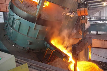
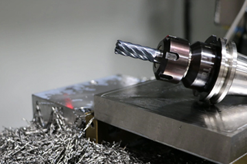
Procuring raw stock, machining precision components, and executing qualified surface treatments across fractured vendor networks introduces elevated scrap rates, tolerance stack-up errors, and cross-contamination hazards. Establishing process repeatability requires an integrated metallurgical perspective that controls chemical composition from the initial primary melt through final anodic oxidation. This technical guide delivers comprehensive empirical parameters, kinetic models, bath chemistry formulations, and operational boundaries necessary to qualify and control industrial titanium anodizing production lines.
Table of Contents
2. Anodic Oxide Growth Rate (1.5 nm/V to 2.2 nm/V) and Optical Interference Spectrum
3. Crystalline Phase Transitions: Amorphous TiO2 to Anatase and Rutile Dielectric Breakdown
4. Industrial Electrolyte Formulations & Comparative Bath Matrix
5. Phosphoric Acid (H3PO4, 5% – 15% wt) for Medical Device Color Coding (Type III)
6. Sulfuric Acid (H2SO4, 10% – 20% wt) and Ammonium Sulfate Formulations
7. Alkaline Electrolytes (KOH, NaOH, Na3PO4, pH ≥ 13) for AMS 2488F Type II Anti-Galling
8. Organic Acids & Boric-Tartaric Modifiers for Pore Sealing and Arc Suppression
9. Pre-Treatment Surface Conditioning & Substrate Metallurgical Integrity
10. HNO3/HF Ratio Control (10:1 Nitric to Hydrofluoric Acid) per ASTM B600
12. Operational Boundaries, Failure Modes & Quality Assurance Protocols
13. Fluoride Ion Carryover, Halide Pitting, and Bath Temperature Ceilings (18°C – 24°C)
14. Galvanic Racking Requirements (CP Grade 2 Titanium Tooling) & Verification Testing
15. Frequently Asked Questions on Titanium Anodizing Electrolytes
17. Technical Consultation & Mill Test Certificate (MTC) Requests
Electrochemical Fundamentals & Oxide Growth Kinetics
The electrochemical oxidation of titanium is governed by high-field ionic conduction across an expanding titanium dioxide (TiO2) barrier layer. Under an externally applied positive electric potential, the titanium metal serves as the anode, while an inert conductor—typically grade 316L stainless steel, pure platinum, or platinized niobium—acts as the cathode. The initial anodic reaction involves the field-assisted ionization of zero-valent titanium into tetravalent cations at the metal-oxide interface: Ti → Ti4+ + 4e-. Concurrently, water molecules within the aqueous electrolyte undergo catalytic dissociation at the oxide-electrolyte interface: 2H2O → O2- + 4H+ + O2(g) + 4e-.
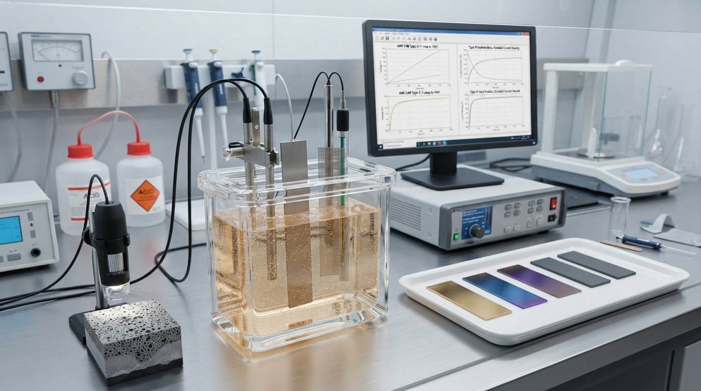
The overall thermodynamic reaction proceeds as Ti + 2H2O → TiO2 + 4H+ + 4e-, generating a Gibbs free energy change of ΔG° = -888.8 kJ/mol at 298 K. Oxide growth requires the continuous physical migration of ions across the dielectric barrier. High electric fields, typically on the order of 106 to 107 V/cm, lower the activation energy barrier for ion jumping through the non-conductive titania lattice. Inward-migrating oxygen anions (O2-) and outward-migrating titanium cations (Ti4+) move simultaneously along point defects and oxygen vacancies. Growth occurs concurrently at both boundaries: new TiO2 forms at the metal-oxide interface via inward oxygen diffusion, and at the oxide-electrolyte interface via outward titanium migration.
As the barrier layer thickens, the internal electric field strength decreases exponentially under constant voltage conditions according to the Cabrera-Mott high-field conduction model: i = i0 exp(B × E), where i represents the ionic current density, E is the applied electric field (E = V/d, with V being voltage and d being film thickness), and i0 and B are temperature- and material-dependent kinetic parameters. Consequently, oxide film growth is strictly self-limiting. At any given constant voltage, once the film reaches its equilibrium thickness, the electric field diminishes to a level where ionic conduction ceases, dropping the residual leakage current to a steady-state minimum (typically < 0.05 A/dm²). This precise self-limiting behavior forms the physical foundation of thin-film optical interference color control.
Anodic Oxide Growth Rate (1.5 nm/V to 2.2 nm/V) and Optical Interference Spectrum
The final physical thickness (d) of an anodic titania film generated in barrier-forming acidic or neutral electrolytes is linearly proportional to the applied forming voltage (V): d = α × V. The proportionality constant α, termed the anodic oxide growth rate, typically falls between 1.6 nm/V and 2.2 nm/V for commercially pure Titanium Metal Grades, governed by electrolyte conductivity, temperature, and current density. On dual-phase alloys such as Ti-6Al-4V, the effective growth constant decreases to approximately 1.5 nm/V to 1.8 nm/V due to localized current shunting and preferential dissolution of solute elements within the beta phase.
The colors generated during Type III titanium anodizing do not arise from dyes, pigments, or chemical stains. They are generated purely by thin-film optical interference, analogous to the colors observed on thin oil slicks on water. When incident ambient white light strikes the anodized surface, a portion of the light wave reflects off the outer air-TiO2 boundary, experiencing a 180° (π radians) phase change because the refractive index of titania (n ≈ 2.2 to 2.6) is significantly higher than that of air (n ≈ 1.0). The remaining fraction of the light wave refracts into the dielectric TiO2 layer, travels to the metal-oxide boundary, and reflects off the metallic titanium substrate (which also induces a phase shift). If the total optical path difference 2nd cos(θ) satisfies the constructive interference condition (2nd cos(θ) = (m - 1/2)λ, where m is an integer and λ is the wavelength), that specific wavelength is reinforced, while competing wavelengths undergo destructive cancellation.
| DC Forming Voltage (V) | Theoretical TiO2 Thickness (nm) | Dominant Constructive Wavelength (nm) | Apparent Color (CP Grade 2) | Chromatic Shift on Grade 5 (Ti-6Al-4V) |
|---|---|---|---|---|
| 12 – 15 | 22 – 28 | 400 – 430 | Silver-Bronze / Faint Straw | Muted Gray-Bronze; requires +2.0 V offset |
| 20 – 25 | 35 – 45 | 460 – 480 | Deep Golden Brown | Slightly darker, lower specular reflectance |
| 30 – 35 | 55 – 65 | 500 – 540 | Dark Purple / Violet | Dull Violet; shifts toward dark blue-violet |
| 40 – 48 | 75 – 88 | 440 – 470 (2nd order) | Deep Royal Blue | Navy Blue; saturation reduced by 15% |
| 55 – 65 | 105 – 120 | 490 – 520 (2nd order) | Cyan / Sky Blue | Dull Cyan-Green; higher diffuse scattering |
| 70 – 78 | 130 – 145 | 570 – 590 (2nd order) | Canary Yellow | Mustard Yellow; highly sensitive to surface Ra |
| 85 – 92 | 160 – 175 | 630 – 660 (2nd order) | Rose Pink / Magenta | Muted Rose; requires +3.5 V to match CP2 hue |
| 98 – 110 | 190 – 215 | 520 – 550 (3rd order) | Apple Green / Emerald | Olive-Green; micro-arcing risk increases significantly |
The refractive index (n) of the anodic layer is not strictly constant; it varies based on density and crystalline phase, shifting from n ≈ 2.15 for disordered amorphous titania formed below 40 V to n ≈ 2.52 for crystalline anatase formed at higher potentials. Consequently, identical voltage settings applied to substrates with disparate surface topographies or alloy compositions yield perceptible chromatic differences (measured as ΔE in the CIE Lab* colorspace), requiring empirical voltage mapping for each specific raw material melt lot.
Crystalline Phase Transitions: Amorphous TiO2 to Anatase and Rutile Dielectric Breakdown
At forming potentials below approximately 50 V, anodic titania deposits as a homogeneous, structurally disordered, amorphous thin film. This amorphous matrix exhibits high electrical resistivity, isotropic mechanical characteristics, and low internal stress, providing exceptional optical transparency necessary for vivid interference colors. However, as the forming voltage climbs beyond 50 V to 60 V, the intense electrostatic field across the thinning dielectric barrier, coupled with localized Joule heating, supplies sufficient activation energy to initiate solid-state nucleation of crystalline anatase (tetragonal crystal structure, space group I41/amd).
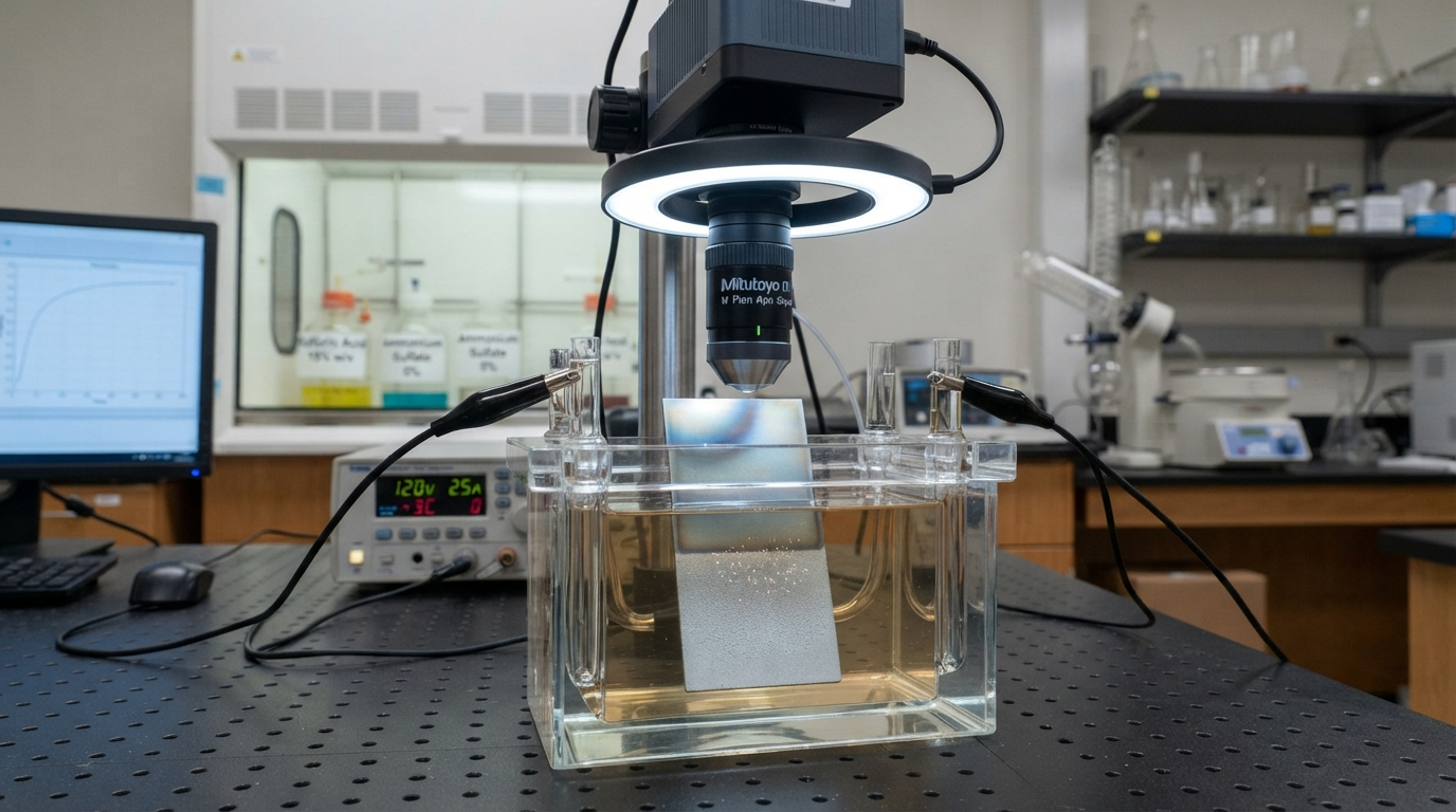
The nucleation of anatase within the amorphous precursor induces an abrupt localized volume contraction of approximately 8% to 10%, generating severe internal tensile stresses. These localized stresses cause micro-cracking at grain boundary interfaces within the oxide layer. Simultaneously, the dielectric constant (εr) shifts dramatically: amorphous TiO2 exhibits an εr of approximately 30 to 40, whereas anatase reaches 48 to 110 along varying crystallographic axes. As crystalline domains grow, electron conduction pathways open through localized defect states, accelerating the rate of oxygen evolution: 2H2O → O2 + 4H+ + 4e-. Gas bubble nucleation beneath the oxide disrupts film uniformity, giving high-voltage colors (such as 90 V pinks and greens) a slightly diffuse, haze-like appearance compared to low-voltage gold or blue hues.
When the applied potential exceeds the electrolyte-dependent dielectric breakdown threshold (typically 100 V to 125 V in phosphoric baths, but as low as 80 V to 85 V in sulfuric acid), the barrier layer experiences complete avalanche breakdown. The localized electric field exceeds the dielectric strength of the titania matrix (approximately 4 × 10⁶ V/cm to 8 × 10⁶ V/cm), producing visible micro-arc discharges (sparks) across the metal surface. These localized thermal spikes exceed 1500°C within sub-micron channels, driving a second, irreversible phase transition: crystalline anatase converts into high-density rutile (tetragonal, space group P42/mnm, εr ≈ 170). The localized melting and thermal quench cause catastrophic film destruction, resulting in porous, ceramic-like scorch craters, severe pitting, and uncontrolled macroscopic roughness that completely destroys optical interference and strips tolerance compliance.
Industrial Electrolyte Formulations & Comparative Bath Matrix
Selecting the optimal industrial electrolyte requires balancing the functional objective of the surface modification—whether thin-film optical interference, baseline corrosion passivation, or heavy-duty tribological anti-galling—against operational risks including dielectric breakdown, heat dissipation, and hydrogen pickup. Standard industrial electrolytes separate cleanly into three primary operational categories: low-conductivity weak organic/inorganic acids, high-conductivity strong mineral acids, and highly concentrated alkaline chelating solutions.
| Electrolyte Category | Nominal Concentration (% wt or M) | Operational pH Range | Bath Temperature (°C) | Current Density (A/dm²) | Governing Standards |
|---|---|---|---|---|---|
| Dilute Phosphoric Acid (H3PO4) | 5.0% – 15.0% wt (0.5M – 1.6M) | 1.2 – 2.0 | 18°C – 24°C | 0.5 – 1.5 A/dm² | ASTM F86, ISO 13485, ASTM F136 |
| Sulfuric Acid (H2SO4) | 10.0% – 20.0% wt (1.1M – 2.3M) | 0.2 – 0.8 | 15°C – 22°C | 1.0 – 3.0 A/dm² | ISO 8080, MIL-A-8625 (titanium equivalents) |
| Ammonium Sulfate ((NH4)2SO4) | 8.0% – 12.0% wt (0.6M – 1.0M) | 5.0 – 6.5 | 20°C – 25°C | 0.5 – 2.0 A/dm² | Commercial Aerospace, ASTM B348 |
| Heavy Alkaline (KOH / NaOH / Na3PO4) | 10.0% – 25.0% wt (Total Alkalinity) | ≥ 13.0 | 20°C – 30°C | 1.5 – 5.0 A/dm² | SAE AMS 2488F (Type II), ISO 965 |
The choice of electrolyte dictates both the maximum attainable dielectric breakdown voltage and the chemical purity of the resulting oxide. Strong mineral acids, while highly conductive and economical for low-voltage coloration, suffer from lower dielectric breakdown limits due to aggressive anion migration. Conversely, buffered phosphate and tartrate chemistries offer widened voltage processing windows at the expense of requiring dedicated active bath chilling systems to dissipate localized Joule heating.
Phosphoric Acid (H3PO4, 5% – 15% wt) for Medical Device Color Coding (Type III)
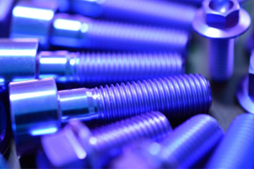
Dilute orthophosphoric acid (H3PO4) remains the international benchmark electrolyte for Type III medical implant color coding governed by ASTM F86. The process converts the surface of trauma plates, spinal rods, and cortical bone screws machined from medical-grade Titanium Bar into vivid, durable, and highly identifiable color states. Orthophosphoric acid is uniquely suited for this purpose due to the chemical incorporation of phosphate anions (PO43-) into the expanding outer titania lattice during ionic conduction.
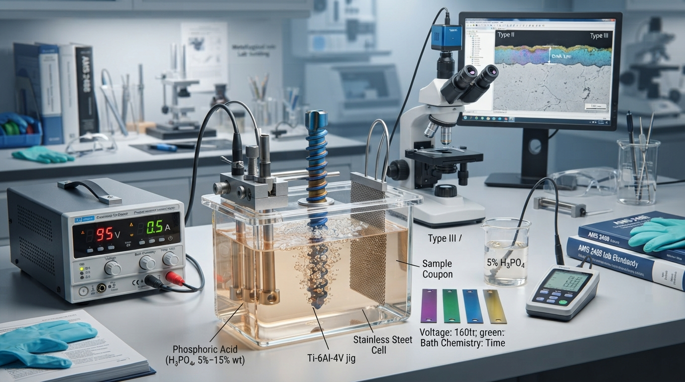
The incorporation of phosphate groups disrupts the continuity of the crystalline lattice, strongly suppressing the premature nucleation of anatase. By retaining an amorphous, highly dielectric structure up to elevated potentials, phosphoric acid baths support stable, uniform oxide growth up to 110 V to 115 V without dielectric breakdown. This allows repeatable production of high-order second- and third-order optical interference bands, specifically the vivid 85 V magenta and 100 V emerald green states critical for distinguishing left/right orthopedic implant components or thread pitch profiles in surgical operating suites.
Furthermore, phosphoric acid anodizing satisfies strict biocompatibility standards. Residual phosphates on the titania surface mimic bone mineral chemistry, actively promoting hydroxyapatite nucleation in vivo without releasing cytotoxic ions. To maintain reproducible chromatic values (ΔE ≤ 1.2), industrial bath control must strictly maintain the H3PO4 concentration between 8% and 12% by weight, keep dissolved titanium below 8 g/L, and regulate bath temperature within 20°C ± 2°C using closed-loop titanium heat exchangers.
Sulfuric Acid (H2SO4, 10% – 20% wt) and Ammonium Sulfate Formulations
Sulfuric acid (H2SO4) electrolytes, widely utilized in high-volume aerospace fastener lines, are characterized by high ionic conductivity and low internal electrical resistance. Operating typically at concentrations of 150 g/L to 200 g/L (approximately 10% to 15% wt), these baths support rapid oxide growth rates under low applied potentials. Equilibrium film thickness is achieved within 15 to 45 seconds at current densities between 1.5 A/dm² and 2.5 A/dm². This rapid processing cycle minimizes tank dwell times for components produced via high-speed Titanium CNC Machining.
However, the aggressive nature of the sulfate anion (SO42-) introduces significant operational trade-offs. The higher mobility and chemical aggressiveness of sulfate ions promote rapid dissolution-assisted crystallization. Consequently, the dielectric breakdown voltage in sulfuric acid electrolytes is drastically lower than that of phosphoric baths, typically capping stable operation at 75 V to 85 V. Attempting to achieve high-voltage green or pink interference colors in a pure H2SO4 bath leads to catastrophic localized micro-arcing, severe burning, and pitting corrosion.
To mitigate this limitation while retaining favorable conductivity, aerospace processors frequently deploy near-neutral ammonium sulfate ((NH4)2SO4) baths at concentrations of 80 g/L to 120 g/L (pH 5.0 to 6.2). The higher bath pH significantly lowers the chemical dissolution rate of the newly forming TiO2 barrier layer, dampens localized Joule heating, and elevates the dielectric sparking ceiling to approximately 95 V. Ammonium sulfate also provides a non-hazardous, easily treated effluent stream that simplifies environmental compliance for high-capacity manufacturing facilities.
Alkaline Electrolytes (KOH, NaOH, Na3PO4, pH ≥ 13) for AMS 2488F Type II Anti-Galling
SAE AMS 2488F Type II anodizing operates on an electrochemical mechanism distinct from acidic Type III interference coloring. While Type III builds a thin, smooth, non-porous optical film, AMS 2488F produces a heavy, matte-gray, micro-porous conversion layer between 1.0 μm and 2.5 μm in thickness, engineered specifically to eliminate titanium-on-titanium and titanium-on-steel galling under severe frictional contact stresses. Uncoated titanium exhibits an extreme tendency to gall, fret, and seize under contact pressures as low as 15 MPa due to its low thermal conductivity, high chemical reactivity with mating metals, and unstable shear planes under friction.
The AMS 2488F electrolyte is strongly alkaline, requiring a operating pH of 13.0 or higher. The bath consists of a concentrated blend of potassium hydroxide (KOH, 150 g/L to 250 g/L) or sodium hydroxide (NaOH), combined with buffering and chelating agents including trisodium phosphate (Na3PO4, 30 g/L to 60 g/L), alkali silicates, or sodium tartrate. The process operates under constant current density control (1.5 A/dm² to 3.5 A/dm²) until the potential reaches a compliance limit of 80 V to 110 V, after which voltage is held constant while current decays toward zero. In this high-pH environment, the titanium surface undergoes continuous chemical dissolution (forming soluble titanates: Ti + 4OH- → TiO44- + 2H2) counterbalanced by field-assisted electrochemical precipitation. This dynamic equilibrium yields a dense, crystalline rutile-anatase composite layer that penetrates into the substrate while growing outward.
A non-negotiable requirement of AMS 2488F Type II processing is the post-anodize removal of the powdery outer transformation layer, referred to as "anodic slough." As the thick oxide conversion builds, the outermost 0.5 μm to 1.0 μm becomes loosely adherent and friable. If left unaddressed, this slough detaches during service, acting as an abrasive third-body contaminant that accelerates severe wear. Processing facilities must incorporate a mandatory post-anodize mechanical cleaning stage, utilizing wet micro-slurry blasting with 400-mesh alumina or intense ultrasonic agitation (25 kHz to 40 kHz at ≥ 15 W/L) in hot deionized water. The remaining dense, adhering conversion layer acts as an ideal mechanical key for dry film lubricants (such as MoS2 per AS5272), providing sustained anti-galling performance under contact loads exceeding 450 MPa.
Organic Acids & Boric-Tartaric Modifiers for Pore Sealing and Arc Suppression
To bridge the operational gap between the high breakdown resistance of phosphoric baths and the high electrical efficiency of sulfate chemistries, advanced anodizing lines utilize organic acid electrolytes and boric-tartaric acid (BTA) modifiers. Organic carboxylate systems based on citric acid (C6H8O7, 10% to 20% wt), oxalic acid (C2H2O4, 5% to 10% wt), or DL-tartaric acid act as mild, non-toxic electrolytes capable of high dielectric stability up to 130 V DC.
The addition of boric acid (H3BO3, 15 g/L to 40 g/L) to dilute sulfuric or phosphoric anodizing baths serves as a localized dielectric field dampener. Borate anions concentrate within sub-microscopic surface defects, localizing the dielectric barrier and suppressing early electron avalanche mechanisms. This arc suppression effect effectively eliminates edge burning on sharp CNC-machined features (such as razor-thin surgical cutting edges or precision fastener hex sockets), raising the sparking threshold by 12 V to 18 V across all titanium grades.
Additionally, proprietary organic modifiers provide in-situ pore consolidation. During high-voltage processing (95 V to 120 V), the rate of gas evolution can create microscopic pinhole porosity in the upper third of the oxide layer, which scatters light and causes optical clouding. Complex organic anions with large molecular weights buffer the electrical double layer at the metal-solution interface, suppressing erratic localized Joule spikes. This mechanism produces dense, optically uniform third-order magenta and emerald-green interference layers with long-term resistance to optical degradation from repeated autoclave sterilization cycles.
Pre-Treatment Surface Conditioning & Substrate Metallurgical Integrity
Empirical testing across aerospace and orthopedic finishing lines indicates that over 80% of titanium anodizing defects—including color blotchiness, premature dielectric arcing, poor adhesion, and flaking—originate from substandard pre-treatment and mechanical surface conditioning rather than anodizing tank chemistry. Titanium is an intensely reactive transition metal that spontaneously forms a native, non-uniform air-formed passivating oxide film (primarily TiO2, 2 nm to 5 nm thick) within milliseconds of exposure to atmospheric oxygen.
Furthermore, machining, drawing, and grinding operations leave heavily distorted, mechanically smeared metal layers on the component surface, frequently loaded with embedded chlorinated machining fluids, carbonaceous residue, and micro-iron particulate contaminants. If an engineered anodic conversion is attempted directly over this contaminated substrate, the uneven electrical conductivity of the native film and surface impurities causes non-uniform current distribution, erratic oxide growth constants, and immediate lot-to-lot color shifts (ΔE > 3.0).
Substrate metallurgical integrity is equally critical. For components requiring consistent anodic behavior, the starting material must be fully traceable back to triple-melted Vacuum Arc Remelted (VAR) or Electron Beam Cold Hearth Melted (EBCHM) ingots. Subsurface metallurgical defects—including high-density inclusions (HDI) from broken carbide tooling or low-density nitrogen-rich interstitial defects (Type I hard alpha)—exhibit disparate work functions and dielectric breakdown limits, creating localized dielectric punctures during anodization that result in part rejections during fluorescent penetrant inspection (FPI per ASTM E1417).
HNO3/HF Ratio Control (10:1 Nitric to Hydrofluoric Acid) per ASTM B600
To establish a clean, chemically active metallic titanium surface for anodization, native oxides and smeared metal must be chemically stripped using an aqueous mixture of nitric acid (HNO3) and hydrofluoric acid (HF) governed by ASTM B600. The active chemical dissolution of the titanium substrate is driven by the aggressive action of hydrofluoric acid: 2Ti + 6HF → 2TiF3 + 3H2(g) or Ti + 6HF → H2TiF6 + 2H2(g). However, this rapid reduction reaction generates copious volumes of nascent, atomic hydrogen (H0) directly at the exposed metallic surface.
If atomic hydrogen is permitted to dwell at the titanium surface, its minute atomic radius enables rapid solid-state interstitial diffusion into the hexagonal close-packed (HCP) alpha titanium crystal lattice. At room temperature, hydrogen diffusion into titanium leads to the precipitation of brittle, needle-like titanium hydride (TiH2) platelets along grain boundaries. This precipitation causes catastrophic hydrogen embrittlement, drastically reducing dynamic fatigue life and inducing delayed brittle cracking under service stresses. To prevent this failure mode, the pickling bath must maintain a strict, non-negotiable minimum chemical ratio of 10:1 nitric acid to hydrofluoric acid by weight (e.g., 20% to 35% wt HNO3 to 2% to 3.5% wt HF).
Under this controlled stoichiometry, the excess nitric acid serves as a powerful oxidizing agent that shifts the redox kinetics at the substrate interface: 2Ti + 6HF + 4HNO3 → 2H2TiF6 + 4NO2(g) + 4H2O. Nitric acid immediately oxidizes the nascent atomic hydrogen into harmless water (H2O) before it can enter the metallic crystal lattice. Substrate testing per ASTM F1113 and inert-gas fusion thermal conductivity analysis (LECO) must verify that hydrogen pickup during pre-treatment remains negligible, keeping total bulk hydrogen strictly below 0.015% (150 ppm) for Grade 5 and below 0.0125% (125 ppm) for Grade 23 ELI alloys.
Substrate Alloy Effects: CP Titanium (Grade 1–4) vs. Alpha-Beta (Grade 5 / Ti-6Al-4V ELI) Color Shift
A common pitfall in industrial titanium anodizing is the assumption that identical electrolyte formulations and voltage parameters will yield identical chromatic and functional results across differing titanium alloys. In practice, substrate phase constitution exerts a governing influence on the electrochemical efficiency and optical interference properties of the grown film. Commercially Pure (CP) titanium grades (UNS R50250 through R50700) possess an essentially single-phase alpha (α) HCP microstructure, whereas Grade 5 (Ti-6Al-4V, UNS R56400) and Grade 23 (Ti-6Al-4V ELI, UNS R56401) are dual-phase alpha-beta (α+β) alloys containing approximately 6% aluminum (an alpha stabilizer) and 4% vanadium (a beta stabilizer).
During anodic polarization, these distinct metallurgical phases react at disparate electrochemical rates. The alpha phase, rich in titanium and aluminum, oxidizes rapidly to form a dense composite barrier of TiO2 and Al2O3. Conversely, the body-centered cubic (BCC) beta phase, enriched in vanadium up to 10% to 15% locally, oxidizes into unstable vanadium pentoxide (V2O5) and vanadium tetroxide (V2O4). Vanadium oxides are chemically unstable in acidic electrolytes and dissolve rapidly into the bath: V2O5 + 2H+ → 2VO2+ + H2O. This localized dissolution creates high-density micro-porosities and vacancy defects directly above the beta grains.
The dissolution of vanadium oxides degrades optical performance in two distinct ways: (1) It alters the effective refractive index of the dielectric barrier, and (2) it causes diffuse internal scattering of incident light waves. Consequently, Grade 5 components exhibit lower color luminance (CIE L* values are typically 8% to 14% lower than on CP Grade 2), yielding darker, more muted, and less saturated hues. Furthermore, the higher electrical conductivity of the beta phase shunts current, reducing the effective growth constant to approximately 1.55 nm/V compared to 1.95 nm/V on CP Grade 2. To achieve an identical optical interference color on Grade 5 as on Grade 2, an empirical voltage boost of +2.0 V to +5.0 V DC is strictly required.
Operational Boundaries, Failure Modes & Quality Assurance Protocols
Maintaining qualified operational status on an industrial titanium anodizing line requires rigorous monitoring of tank contamination, chilling efficiency, and process electrical control. Deviations in physical parameters trigger characteristic failure modes that undermine the corrosion, tribological, or aesthetic integrity of the product. Industrial facilities must operate under ISO 13485 or AS9100D certified quality management systems, complete with raw material traceability backed by certified EN 10204 3.1 Mill Test Certificates.
Failure modes typically stem from three contamination vectors: process chemical cross-contamination, thermal runaway due to insufficient chilling capacity, and localized dielectric breakdown triggered by halide accumulation. Establishing quantifiable rejection criteria and automated shutdown limits prevents costly batch-level scrapping during high-value manufacturing runs.
Non-destructive inspection protocols must be integrated directly into post-process operations. These protocols include diffuse reflectance spectrophotometry to quantify color values (verifying ΔE ≤ 1.5 against physical master reference coupons), eddy current film thickness verification per ISO 2360 for thick Type II coatings, and ASTM B117 neutral salt spray testing (surviving 168 hours with zero signs of substrate pitting or color flaking).
Fluoride Ion Carryover, Halide Pitting, and Bath Temperature Ceilings (18°C – 24°C)
The most catastrophic contaminant in an industrial titanium anodizing bath is the fluoride ion (F-). Following pre-treatment activation in ASTM B600 nitric-hydrofluoric pickling tanks, complex fluoro-titanate complexes and free fluoride ions adhere aggressively to component surfaces, blind tapped holes, and interior channels. If rinsing stages are poorly managed, drag-in introduces fluoride into the main anodizing tank.
Within the anodizing cell, free fluoride acts as an active depassivator. Titanium dioxide instantly dissolves in the presence of even trace fluoride: TiO2 + 6F- + 4H+ → [TiF6]2- + 2H2O. If the fluoride concentration within the anodizing electrolyte exceeds 50 ppm (0.005% wt), localized dissolution outpaces the electrochemical growth rate. At potentials exceeding 60 V, this dynamic dissolution-growth conflict triggers severe halide pitting corrosion: high-intensity current channels through the weakened barrier, causing catastrophic localized burning, macro-cratering, and destruction of finished tolerances. Preventing fluoride carryover requires multi-stage counter-current cascade rinses utilizing ASTM D1193 Type I or Type II deionized water (conductivity < 1.0 μS/cm, resistivity ≥ 1.0 MΩ·cm), backed by routine potentiometric ion-selective electrode (ISE) bath testing.
Simultaneously, bath temperature must be actively regulated via automated chilling units. High-field ionic conduction across the dielectric barrier generates significant localized Joule heating (Q = I²Rt). As bath temperature rises above 24°C, the chemical dissolution rate of the newly forming amorphous titania accelerates exponentially. If bulk electrolyte temperature exceeds 28°C to 30°C, the elevated thermal energy drives premature nucleation of anatase, causing rapid oxygen evolution, hazy milky discoloration, non-uniform film growth, and powdery surface sloughing. Industrial anodizing lines must maintain bath temperatures between 18°C and 22°C (± 1.0°C) using titanium or Teflon-coated heat exchangers.
Galvanic Racking Requirements (CP Grade 2 Titanium Tooling) & Verification Testing
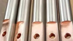
Tooling and racking selection for titanium anodizing requires careful galvanic and structural consideration. A catastrophic mistake in job-shop finishing is utilizing aluminum, copper, or steel racking fixtures inside a titanium anodizing cell. Unlike aluminum, which forms a thick insulating porous oxide, or copper, which dissolves instantly into the acid, titanium parts require racks constructed exclusively from Commercially Pure Grade 2 Titanium Wire, heavy-gauge titanium strip, or high-conductivity Titanium-Copper Clad Bar systems.
The primary advantage of pure titanium racking is its self-passivating capability. During the initial anodizing cycle, the titanium rack builds the identical self-limiting dielectric TiO2 film as the workpiece. Once passivated, the rack draws virtually zero electrical current on subsequent runs, directing 100% of the input amperage exclusively through the clamped contact points into the workpiece. However, because the rack surface is non-conductive, electrical contact points must provide positive mechanical spring tension. Loose contact points cause high interface resistance, generating intense localized arcing that scorches the component contact area and creates uncolored contact shadows.
Purchase Order (PO) Quality Assurance Specification Checklist
Substrate Baseline Verification: Full EN 10204 3.1 Mill Test Certificate tracing 3x VAR melt ingot; bulk interstitial hydrogen verified ≤ 125 ppm per ASTM F1113.
Surface Cleanliness: Zero residual alpha-case layer (100% chemical descaling per ASTM B600); baseline surface roughness verified Ra ≤ 0.4 μm prior to anodization.
Anodizing Type & Standard: Explicitly state "AMS 2488F Type II Anti-Galling" or "ASTM F86 Type III Interference Color Coding (Target Color: Blue 44V / Pink 88V)".
Post-Process Requirements: For Type II, verify 100% mechanical slough removal via wet micro-blast or ultrasonic agitation; for Type III, confirm spectrophotometric lot tolerance ΔE ≤ 1.5.
Deionized Water Cascade: Post-anodize rinse in deionized water (resistivity ≥ 1.0 MΩ·cm) followed by cleanroom-grade filtered dry nitrogen packaging.
Frequently Asked Questions on Titanium Anodizing Electrolytes
Why do household baking soda (NaHCO3) and retail TSP fail aerospace and medical anodizing audits?
While consumer-grade sodium bicarbonate (baking soda) and retail trisodium phosphate (TSP) can induce rudimentary optical interference colors, they are entirely unacceptable for qualified aerospace (AMS 2488) or medical (ASTM F86) manufacturing. Retail chemical formulations contain uncontrolled impurities—notably chlorides, silicates, and heavy metal ions—that promote localized halide pitting and dielectric breakdown above 40 V. Furthermore, unbuffered sodium bicarbonate exhibits poor ionic conductivity and variable pH, resulting in rapid current drop-off, inconsistent film growth rates (α varying widely across a single workpiece), and extreme lot-to-lot color drift (ΔE > 5.0). Qualified industrial lines deploy technical-grade reagents mixed with ultra-pure ASTM D1193 Type I deionized water (≥ 10 MΩ·cm) to eliminate uncontrolled ionic contamination.
How do you strip and re-anodize rejected titanium parts without violating tight dimensional tolerances?
Stripping an anodic titania film without attacking the underlying metallic substrate requires precise chemical bath control. Standard nitric-hydrofluoric pickling baths dissolve the parent metal at rates of 0.005 mm to 0.025 mm per minute, destroying precision-machined thread profiles, bearing journals, and tight bore tolerances. The qualified industrial method utilizes an aqueous solution of ammonium bifluoride (NH4HF2, 30 g/L to 50 g/L) buffered with concentrated nitric acid (HNO3, 200 g/L to 300 g/L) at room temperature (20°C). This buffered chemistry strips the thin 50 nm to 200 nm interference oxide within 5 to 15 seconds while maintaining parent metal stock loss below 0.001 mm (1.0 μm) per surface. Following thorough deionized water cascade rinsing, parts can be immediately re-anodized without tolerance non-conformance.
Why is it physically impossible to achieve a true, vibrant red through titanium interference anodizing?
A true, saturated primary red cannot be generated on titanium via interference anodizing due to the physics of multi-order optical wave interference. As the anodic oxide film thickens toward the red spectral window (approximately 160 nm to 180 nm, achievable between 85 V and 95 V), the optical path difference 2nd cos(θ) concurrently satisfies constructive interference conditions for lower-order blue and violet wavelengths (second-order interference). Consequently, the human eye perceives a combination of reflected red and newly emerging higher-order blue wavelengths, resulting in magenta, rose, or pink hues rather than a primary spectrum red. Deep saturated reds can only be produced on aluminum (which absorbs red organic azo dyes into its thick porous structure) or via thermal oxidation methods that compromise substrate fatigue strength.
Should a titanium anodizing rectifier be controlled via constant voltage or constant current density?
Industrial titanium anodizing requires a coordinated hybrid control methodology: initial current density ramping followed by terminal constant voltage limiting. If a component is subjected to an instantaneous high-voltage step (e.g., plunging a part into a 90 V bath), the surge of instantaneous current through the thin native oxide generates immense localized Joule heating, causing dielectric breakdown, arcing, and pitting. The qualified approach ramps current at a controlled rate (typically 0.5 A/dm² to 1.5 A/dm² per minute) until the pre-determined target voltage is achieved. Once the target voltage is reached, the rectifier switches to constant voltage control; the self-limiting nature of barrier-layer growth causes current to decay exponentially toward zero. Once current stabilizes at baseline (< 0.05 A/dm²), the cycle is complete.
Related Technical Specifications & Material Grade Hub
China Titanium Factory maintains vertically integrated manufacturing controls spanning primary melt processing, precision forging, centerless bar grinding, ultra-high-speed CNC Swiss machining, and certified surface treatment lines. Standardizing on single-source manufacturing eliminates split liability between raw material suppliers, precision machine shops, and finishing job shops, ensuring full traceability and zero dimensional rejection.
| Material Grade / Product Line | Primary Standard Specifications | Key Metallurgical Attributes | Anodizing Compatibility & Optimal Fit |
|---|---|---|---|
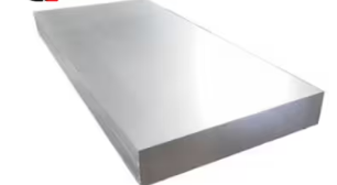
| Titanium Metal Grades | ASTM B265, ASTM B348, AMS 4911, AMS 4928 | Full series from CP Grade 1 to Beta-C; VAR melted with certified low interstitials. | Primary stock for precision anodized assemblies; custom melt chemistry for color matching. |
| Titanium CNC Machining | AS9100D, ISO 13485, ISO 9001, ISO 2768-mK | 5-axis milling, Swiss turning; pre-anodize tolerance compensation (±0.0025 mm). | Turnkey machined & anodized medical screws, aerospace splines, and subsea fluid couplings. |
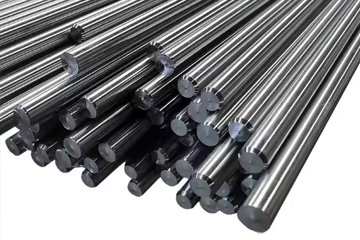
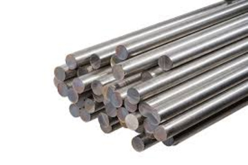
| Titanium Bar | ASTM B348, ASTM F136, AMS 4928, AMS 2631 AA | Centerless ground finish (Ra ≤ 0.4 μm); 100% ultrasonic defect inspection. | Orthopedic implant bar stock; highly uniform surface for repeatable Type III interference colors. |
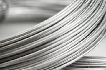
| Titanium Wire | ASTM B863, AWS A5.16, ASTM F67 | Commercially Pure Grade 2 spring-temper; bright annealed, acid-pickled surface. | Standard tooling wire for anodizing racks; zero bath contamination, self-passivating. |
| Titanium-Copper Clad Bar | ASTM B898, Commercial Anodizing Tank Standards | Explosion-bonded or hot-extruded OFHC copper core with CP Grade 2 titanium cladding. | High-conductivity tank busbars and main rack hook spines; prevents localized voltage drop. |
Technical Consultation & Mill Test Certificate (MTC) Requests
Managing titanium surface conversion chemistry, pre-treatment pickling ratios, and strict tolerance compensations requires precision engineering support. China Titanium Factory eliminates vendor hand-off risks by providing fully integrated raw material manufacturing, precision CNC machining, and qualified anodizing services backed by comprehensive quality documentation.
Our engineering support pathway is structured to accelerate design validation and streamline procurement:
Step 1: Upload 3D CAD/DFM Files: Submit native STEP, IGES, or DWG files directly through our secure engineering portal for immediate tolerance stack-up and pre-anodize etch compensation review.
Step 2: Receive 12-Hour DFM & MTC Dossier: Our application engineers return a complete manufacturability report, tooling contact point plan, and certified EN 10204 3.1 Mill Test Certificate sample confirming low-interstitial chemistries.
Step 3: Direct Metallurgical Consultation: Review production milestones, bath chemistry parameters, or witness coupon dispatch protocols directly via video conference with our Senior Metallurgical Staff.
Direct Engineering Inquiries: sales@chinatitaniumfactory.com | AS9100D & ISO 13485 Certified Production