




















Titanium Strip for Slitting and Stamping: Edge Burr Limits, Camber Tolerances & Anisotropy Control
Continuous coil-fed progressive die stamping and high-speed rotary shear slitting of titanium strip present distinct mechanical challenges driven by the physical metallurgy of hexagonal close-packed (HCP) alpha titanium. Achieving consistent yield during high-speed, multi-station stamping operations requires tight control over raw material thickness tolerances, edge shear-to-fracture morphology, slit edge burr heights, and lateral coil camber. In applications such as deep-drawn proton exchange membrane (PEM) fuel cell bipolar plates, chevron-corrugated plate heat exchanger (PHE) plates, and intricate aerospace spring contacts, minor deviations in interstitial alloying elements or longitudinal residual stresses directly induce edge notch cracking, catastrophic springback drift, or galling on precision tooling steel.
Procuring precision slit titanium strip for automated manufacturing demands an engineering shift away from generic ASTM B265 commercial specifications toward dedicated stamping-grade chemistries and dimensional controls. Standard mill tolerances permit excessive thickness variations and broad mechanical property bands that destabilize progressive tooling. In continuous stamping lines running at 100 to 500 strokes per minute, a 20 MPa drift in yield strength across master coil splices shifts the dynamic neutral axis, causing dimensional deviations that exceed strict geometric dimensioning and tolerancing (GD&T) limits. Consequently, cold-rolling mills must deploy dedicated 20-high Sendzimir rolling passes combined with continuous stretch-bend tension leveling and tightly managed rotary knife clearance ratios.
China Titanium Factory supplies precision-rolled and rotary-slit titanium strip coils configured to suppress common failure modes including edge micro-tearing, twist camber, and deep-drawing earing. By managing interstitial elements—specifically restricting oxygen to between 0.04% and 0.08% for deep-drawing Grade 1—and holding slitting burr heights to ≤ 0.015 mm (≤ 3% of strip thickness) alongside lateral camber ceilings of ≤ 1.0 mm per 2,000 mm, stamping plants can maintain stable bottom-dead-center repeatability across high-volume production cycles.
Metallurgical Baseline for Stamping: Grade Selection & Interstitial Chemistry Control
Cold-forming titanium strip involves fundamentally different deformation mechanics than processing cubic face-centered (FCC) austenitic stainless steels or body-centered cubic (BCC) carbon steels. At ambient temperatures, unalloyed titanium exists in the alpha phase, exhibiting an HCP crystal lattice with an axial ratio of c/a ≈ 1.587. Because this value falls below the ideal close-packed ratio of 1.633, deformation slip does not occur along close-packed basal planes {0001}. Instead, slip operates primarily on {1010} prismatic planes along <1120> directions. Because these prismatic systems offer only two independent slip mechanisms, secondary deformation twinning—specifically {1012} tensile twinning and {1122} compressive twinning—must activate to accommodate general three-dimensional plastic strain without through-thickness tearing.
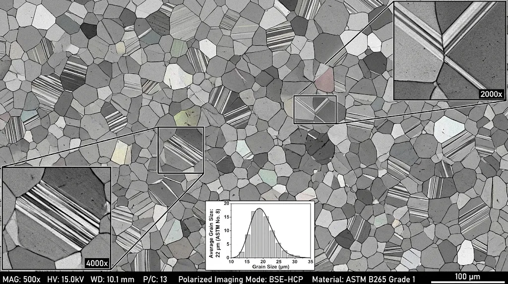
Selecting between Grade 1 and Grade 2 titanium for stamped components involves balancing raw yield strength against ultimate draw depth and tool wear. ASTM B265 Grade 1 represents the purest unalloyed industrial grade. With low interstitial resistance, its yield strength (Rp0.2) operates predictably within 170 to 240 MPa, supported by total tensile elongation (A50) exceeding 30% to 38%. This ductility makes Grade 1 the standard choice for plate heat exchanger (PHE) corrugation patterns and fuel cell bipolar plates with micro-channel draw depths. Conversely, ASTM B265 Grade 2 incorporates higher allowable oxygen levels (up to 0.25% by standard specification, though cold-rolling mills restrict this to 0.14%–0.18%). The higher oxygen concentration shifts baseline yield strength to 275–380 MPa, increasing the required stamping tonnage by approximately 40% and accelerating tool wear on critical draw punch radii.
Formability in progressive stamping depends heavily on the work-hardening exponent (n-value) and the Erichsen cupping index (IE). High-purity Grade 1 titanium strip exhibits an n-value between 0.14 and 0.18 during early uniform plastic strain, which decreases as cold deformation accumulates. When evaluated via ASTM E643 ball-punch deformation testing, precision-rolled Grade 1 strip at 0.5 mm nominal thickness yields an Erichsen cupping depth of 9.5 mm to 11.8 mm prior to localized through-thickness necking. Grade 2 strip typically delivers Erichsen values between 8.0 mm and 9.2 mm under identical punch radius and blank-holding forces. If unalloyed titanium strip is cold-worked past a 35% cumulative reduction without an intervening recrystallization anneal, deformation twinning saturates. This dramatically increases the risk of shear fractures along localized slip bands when subjected to compound multi-axis stamping.
ASTM B265 Grade 1 (Plate/Bipolar Quality) vs. Grade 2 vs. Grade 9 Formability Matrix
To establish baseline tooling inputs for blank development, progressive punch profiles, and springback models, tooling engineers require empirical mechanical datasets. Standard ASTM minimum values are insufficient for precision stamping dies, which require defined operational ranges rather than simple lower limits. The following matrix contrasts China Titanium Factory's cold-rolled and vacuum-annealed strip tempers across unalloyed and lightly alloyed Titanium Metal Grades.
| Alloy Grade & Temper | Yield Strength Rp0.2 (MPa) | Tensile Strength Rm (MPa) | Elongation A50 (%) | Strain Hardening Exponent (n) | Normal Anisotropy (rm) | Erichsen Cupping IE (mm, 0.5t) | Min Bend Radius (MBR, 90°) |
|---|---|---|---|---|---|---|---|
| CP Grade 1 (Stamping Quality) | 170 – 240 | 240 – 350 | 30 – 38 | 0.15 – 0.18 | 3.2 – 4.5 | 10.5 – 11.8 | 0.5t (T) / 1.0t (L) |
| CP Grade 2 (Standard Draw) | 275 – 380 | 345 – 480 | 24 – 32 | 0.12 – 0.15 | 2.4 – 3.2 | 8.5 – 9.8 | 1.0t (T) / 1.5t (L) |
| CP Grade 4 (High Strength) | 480 – 620 | 550 – 740 | 15 – 22 | 0.09 – 0.12 | 1.6 – 2.2 | 6.0 – 7.2 | 2.0t (T) / 2.5t (L) |
| Grade 9 (Ti-3Al-2.5V Annealed) | 520 – 650 | 620 – 760 | 15 – 20 | 0.10 – 0.13 | 1.8 – 2.5 | 5.5 – 6.8 | 2.0t (T) / 3.0t (L) |
Plastic strain ratio measurements, quantified through the Lankford coefficient (r-value), demonstrate the resistance of titanium strip to through-thickness thinning. While deep-drawing automotive steels typically exhibit normal anisotropy values (rm) between 1.4 and 2.0, Grade 1 cold-rolled titanium strip routinely exhibits rm values between 3.2 and 4.5. This high normal anisotropy indicates that the material resists thinning under in-plane tension, instead drawing material across its surface width. However, planar anisotropy (Δr) remains high, necessitating controlled blank profiles to prevent deep-draw earing during cylindrical forming operations.
For operations involving sharp bends, the minimum bend radius (MBR) is anisotropic. Transverse (T) bends—where the bend axis is parallel to the rolling direction—can achieve tighter radii (0.5t for Grade 1) than longitudinal (L) bends (1.0t). This difference stems from the basal texture generated during cold reduction, which aligns the c-axes of the HCP lattice predominantly perpendicular to the rolling direction. Aligning bend axes improperly relative to coil direction causes outer-fiber strain localization, resulting in orange-peel surfaces or micro-cracking.
Interstitial Impurity Caps (O, Fe, N, C, H) to Eliminate Batch-to-Batch Springback Drift
The primary driver of inconsistent springback in automated stamping dies is undocumented variation in interstitial chemistry across incoming material master heats. Interstitial elements occupy octahedral voids within the alpha-titanium HCP lattice, distorting the c/a axial ratio and creating asymmetric stress fields. Oxygen (O) and nitrogen (N) are potent solid-solution strengtheners; each incremental 0.01% (100 ppm) increase in interstitial oxygen raises yield strength by approximately 12 to 15 MPa. This increase elevates the ratio of yield strength to elastic modulus (Rp0.2/E), directly expanding the angular springback envelope during free-bending operations.
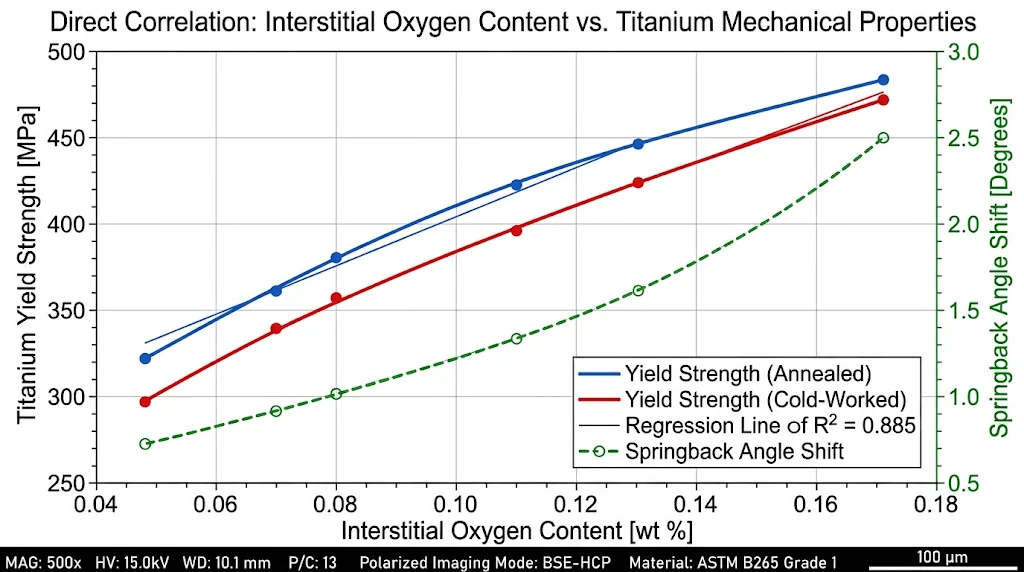
Standard ASTM B265 Grade 1 chemical requirements establish an oxygen ceiling of O ≤ 0.18% and an iron limit of Fe ≤ 0.20%. However, commercial strip delivered near these upper boundaries will exhibit yield strengths exceeding 260 MPa. A stamping tool calibrated for 180 MPa stock will fail when running material with a 260 MPa yield, producing shallow draw depths, out-of-tolerance flange angles, and dimensional rejections. To support predictable progressive die stamping, China Titanium Factory applies restricted interstitial chemistry caps for deep-drawing and fuel-cell applications, narrowing chemical variation to keep yield strength within a tight 35 MPa operational window:
Oxygen (O): 0.040% – 0.080% max (Eliminates localized yield spikes and lattice embrittlement)
Iron (Fe): ≤ 0.060% max (Mitigates beta-phase segregation and localized work-hardening hot spots)
Nitrogen (N): ≤ 0.015% max (Prevents severe prismatic lattice locking)
Carbon (C): ≤ 0.020% max (Prevents titanium carbide TiC precipitation at grain boundaries)
Hydrogen (H): ≤ 0.0050% / 50 ppm (Prevents hydride precipitation and delayed mechanical cracking)
Controlling hydrogen is critical when stamping thin-gauge titanium strip coil (Titanium Foil and strip gauges from 0.05 mm to 0.30 mm). If strip absorbs excessive hydrogen during intermediate acid pickling, titanium hydride platelets (TiHx) precipitate along alpha grain boundaries. Under the high strain rates of progressive dies (100–300 mm/s), these hydrides do not deform plastically; instead, they fracture, initiating micro-voids that coalesce into brittle shear splits. China Titanium Factory utilizes high-vacuum annealing furnaces operating at pressures below 10−3 Pa (10−5 mbar) to ensure finished strip maintains hydrogen levels below 30–50 ppm, safely beneath the 150 ppm ASTM upper limit.
20-High Sendzimir Rolling, Vacuum Annealing & Surface Topography (2B, BA, Matte Pickled)
Achieving gauge uniformity across wide strip profiles requires rigid cold-rolling equipment. Traditional 2-high or 4-high rolling mills experience roll deflection under high separating forces, producing strip with crown—where the center of the strip is thicker than the edges. For precision progressive dies, this profile causes uneven blank-holder pressure, leading to part wrinkling on thin edges and excessive coining forces in the center. China Titanium Factory rolls titanium strip on 20-high Sendzimir cluster mills. This roll configuration uses small-diameter work rolls (typically 30 mm to 55 mm) backed by multi-tier intermediate rolls and heavy-duty backing assemblies housed within a rigid monobloc frame. This design prevents roll bending and enables closed-loop X-ray and laser sensors to hold strip thickness tolerances within ±0.003 mm on gauges under 0.50 mm.
Following cold rolling, strip coils undergo recrystallization vacuum annealing to eliminate deformation textures and restore ductility. Furnaces must run under active turbomolecular pumping to prevent oxygen or nitrogen pickup, which forms a brittle surface alpha-case layer. An alpha-case layer as thin as 2 μm reduces fatigue life and acts as a crack initiation site during stamping bends. Strip is thoroughly degreased prior to furnace charging to prevent residual rolling lubricants from breaking down into carbon or hydrogen contaminants at high temperatures.
Stamping performance also depends directly on finished strip surface topography. Tool galling remains a primary failure mode when forming titanium; matching surface roughness (Ra) to the target lubrication regime is critical:
Bright Annealed (BA) Finish (Ra ≤ 0.12 μm): Produced via high-polish tungsten carbide work rolls and mirror vacuum annealing. Best suited for electronic spring clips, micro-stamped medical connectors, and acoustic diaphragms where maximum contact conductivity or pristine aesthetic quality is required.
2B Cold-Rolled Finish (Ra 0.20 – 0.35 μm): A standard cold-rolled, annealed, and skin-passed surface. Provides a balanced baseline for moderate deep-drawing operations and progressive bending dies.
Matte Acid-Pickled / Micro-Textured Finish (Ra 0.35 – 0.60 μm): Produced via controlled chemical descaling or textured skin-pass rolls. The micro-valleys act as fluid reservoirs that retain high-pressure boundary stamping lubricants (chlorinated paraffin alternatives, synthetic polymers). This mechanism prevents metal-to-metal contact with the die face, suppressing adhesive galling during severe deep drawing.
Precision Rotary Slitting Engineering: Burr Limits, Edge Conditioning & Camber Control
Slitting titanium strip requires different mechanical setups than slitting common mild steels or brass alloys. Titanium exhibits high chemical affinity for cutting tool substrates, a high shear-strength-to-modulus ratio, and low thermal conductivity (16.4 W/m·K, approximately 30% that of carbon steel). As slitter knives shear through titanium coil stock, the localized deformation energy converts almost entirely to heat concentrated at the blade tip. Without proper tool clearances and high-rigidity arbors, the strip edge suffers thermal softening, micro-welding, work-hardened tear fractures, and large burrs that damage progressive dies downstream.
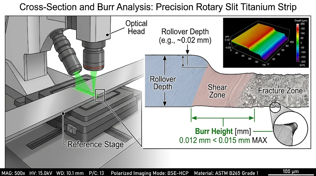
For high-speed progressive die stamping, slit edge quality directly dictates part reliability. A burr on the strip edge acts as an abrasive stress concentrator. As the strip feeds through tight tool guides, edge burrs shed micro-debris into punch clearances, leading to pilot pin binding, sensor faults, and galling on the die shoes. More critically, when stamped components feature stretch-flanged edges, hole expansions, or bent tabs adjacent to the slit perimeter, microscopic tensile tears from the slitting process will propagate into visible edge cracks under dynamic stamping loads.
China Titanium Factory operates CNC-shimless rotary gang slitters equipped with tungsten carbide (WC-Co) knives and dedicated dynamic tension leveling. Setting knife clearances to 5%–8% of strip thickness while running arbor runout below 0.002 mm limits edge burr heights to ≤ 0.015 mm (or ≤ 3% of strip thickness). For automated stamping lines, this delivers clean pilot entry, prevents strip jams, and minimizes press downtime.
Rotary Slitter Knife Clearance (5%–8% Ratio) & Shear-to-Fracture Zone Mechanics
The cross-section of a correctly slit titanium strip exhibits four distinct morphological zones: rollover depth, burnish/shear depth, fracture zone, and exit burr height. The horizontal clearance between male and female rotary knives governs the distribution between the ductile shear zone and the brittle fracture zone. For commercially pure titanium strip, horizontal blade clearance (c) must be maintained between 5% and 8% of strip thickness (t):
| Strip Gauge (t, mm) | Horizontal Clearance (5%–8% t) | Vertical Knife Overlap (h) | Target Shear Zone Depth | Max Burr Ceiling (No. 3 Edge) |
|---|---|---|---|---|
| 0.05 mm – 0.10 mm | 0.003 mm – 0.006 mm | +0.10 mm to +0.25 mm | 45% – 60% of t | ≤ 0.005 mm |
| 0.12 mm – 0.30 mm | 0.008 mm – 0.018 mm | +0.05 mm to +0.15 mm | 40% – 55% of t | ≤ 0.010 mm |
| 0.35 mm – 0.80 mm | 0.020 mm – 0.048 mm | -0.05 mm to +0.05 mm | 35% – 50% of t | ≤ 0.015 mm |
| 0.85 mm – 2.00 mm | 0.050 mm – 0.120 mm | -0.10 mm to -0.30 mm | 30% – 45% of t | ≤ 0.025 mm |
If horizontal clearance drops below 4% of strip thickness, cutting forces spike sharply, inducing secondary shear zones on the sheared face. This secondary shear creates a double-burnished surface alongside rapid work-hardening of the edge, accelerating blade edge chipping. Conversely, when clearance exceeds 10% of strip thickness, the strip bends between the knives under tensile stress rather than shearing cleanly. The material undergoes tensile tearing, yielding an enlarged rollover radius, an angular fracture slope, and high edge burrs.
Slitter blade material selection is critical to maintaining these tolerances over long continuous runs. Standard high-carbon, high-chromium tool steels (such as AISI D2 or 1.2379) degrade rapidly when slitting CP titanium coils due to micro-adhesive wear. We utilize ultra-fine-grained tungsten carbide (WC) or sub-micron powder-metallurgy high-speed steels (ASP 2030 / Vanadis 4 Extra) hardened to 62–64 HRC and polished to Ra ≤ 0.05 μm. These wear-resistant knives prevent material transfer and maintain clean, burr-free edges throughout high-volume slitting runs.
Edge Condition Classifications: No. 3 Slit Edge vs. No. 1 Round Edge vs. No. 5 Deburred Edge
Titanium strip is specified with different edge conditions depending on downstream die guiding systems, component fatigue demands, and secondary joining operations. Standard rotary slitting produces an as-slit edge, but complex progressive stamping dies often benefit from mechanically conditioned edges to minimize feed resistance and prevent localized cracking.
| Edge Specification Code | Manufacturing Method | Burr Height Ceiling | Edge Geometry & Radius | Target Stamping & Forming Fit |
|---|---|---|---|---|
| No. 3 Slit Edge | Precision rotary gang shear (WC blades) | ≤ 0.015 mm (or ≤ 3% of t) | Standard square with natural fracture angle (7°–12°) | Standard continuous progressive stamping; shallow draws. |
| No. 5 Deburred / Skived Edge | Rotary slitting followed by carbide edge skiving knives | ≤ 0.005 mm (Virtually burr-free) | Square conditioned edge; corners chamfered ~45° | Tight progressive die stock lifters; eliminates pilot jamming. |
| No. 1 Round Edge | Multi-pass edge-contour profiling rolls or precision milling | Zero detectable burr (Absolute 0.000 mm) | True full round profile (r = 0.5 × t) across thickness | Severe deep-drawn flanged collars; high fatigue life parts. |
Edge No. 3 represents the standard commercial delivery condition for continuous progressive stamping lines. When stamping parts with critical flanged collars or deep draws near strip borders, however, the micro-fissures in a standard fracture zone can act as stress risers under tangential hoop stresses, leading to edge splitting. Specifying an Edge No. 5 or Edge No. 1 eliminates these micro-notches.
Additionally, Edge No. 1 and No. 5 conditions lower feed friction within precision stamping dies. When running narrow strips (widths under 25 mm) through spring-loaded tool steel stock guides at high speeds, sharp No. 3 slit edges can shave material off the guides. These shavings contaminate the lower die cavity, scoring finished parts and degrading tool surfaces. Mechanically conditioned round or deburred edges track smoothly through progression blocks without galling the tool steel.
Residual Stress Release (Δσresidual), Tension Leveling, Camber & Cross-Bow Limits
A primary failure mode encountered when slitting master coils into narrow mults is lateral camber (edgewise bowing) and helical twist. This deformation is caused by asymmetric residual stresses locked within the material during prior rolling passes. The underlying mechanical failure sequence follows a direct physical pathway: asymmetric cold rolling thickness reductions yield internal longitudinal stress differentials across the strip width (Δσresidual = σedge − σcenter). When a rotary slitter divides the strip into narrow ribbons, these internal balancing moments are released. The strip ribbon responds by undergoing asymmetric elastic recovery, resulting in lateral camber and three-dimensional coil twist.
Left unmanaged, lateral camber forces the strip against die guide rails, misaligning pilot pins and causing punch strikes that damage progressive tooling. To maintain coil straightness, China Titanium Factory subjects all master coils to continuous stretch-bend tension leveling prior to slitting. This process passes the strip through intermeshed work-roll cassettes under precisely controlled axial tension, cycling the outer fibers through alternating plastic-elastic deformation. This mechanical work equalizes internal stress profiles across the width, reducing residual stress differentials to near zero.
| Geometrical Inspection Parameter | ASTM B265 Standard Tolerance | CTF Precision Slit Tolerance Class | Verification Method & Gage Length |
|---|---|---|---|
| Slit Width Tolerance | ±0.25 mm to ±0.80 mm | ±0.03 mm to ±0.08 mm | Laser micrometer / Optical comparator |
| Edge Camber (Lateral Bow) | ≤ 6.35 mm per 2,000 mm length | ≤ 0.8 mm – 1.0 mm per 2,000 mm | Precision granite table with straightedge |
| Cross-Bow (Strip Dishing) | Not rigorously specified | ≤ 0.5% of absolute strip width | Dial indicator transverse depth traversal |
| Strip Flatness (I-Units) | 15 – 30 I-units | ≤ 3 – 5 I-units (Wave height < 0.5 mm) | Calculated steepness factor: I = (πH/2L)² × 10⁵ |
Restricting strip flatness within ≤ 5 I-units is necessary when stamping ultra-thin fuel cell bipolar plates from Titanium Foil coils. Minor transverse cross-bowing will prevent full contact with vacuum feeding cups, destabilize strip alignment across progression stages, and cause localized wrinkling when blank-holder pressure is applied.
Coil Geometry, Winding Architecture & Automated Decoiler Synchronization
In high-speed progressive stamping operations, press uptime depends directly on coil build geometry and decoiler payoff dynamics. Titanium's density (4.51 g/cm³) is roughly 57% that of carbon steel (7.85 g/cm³). While this lower density yields significantly more linear meters per metric ton of raw material, it also alters decoiler payoff inertia, rotational acceleration, and loop-arm brake response times.
Automated stamping lines require clean coil payoff without edge damage, inter-lap binding, or sudden changes in winding tension. In continuous production lines running at 150 strokes per minute with a 25 mm progression pitch, the strip accelerates from complete rest to high feeding velocities within fractions of a second. Uneven coil winding or incorrect arbor expansion forces can lead to surface scratching, coil cinching, or strip feeding misalignments.
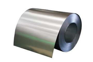
China Titanium Factory supplies slit titanium strip in standardized pancake ribbon coils and traverse oscillated-wound spools. Each format is matched to specific press feeder configurations, core diameters, and run lengths to optimize continuous stamping efficiency.
Pancake (Ribbon-Wound) vs. Traverse Oscillated-Wound Coils for High-Speed Stamping Runs
Stamping plant engineers must select between two primary packaging and winding formats based on strip width, stock thickness, and production volumes:
Pancake (Ribbon-Wound) Coils: Strip is wound concentric upon itself to the desired outer diameter at a uniform width. This is the industry standard for strip widths exceeding 25 mm. However, for narrow widths (under 15 mm) and thin gauges, maximum pancake coil weight is physically constrained to prevent the coil from telescoping or collapsing under its own weight during shipment and decoiler handling.
Traverse Oscillated-Wound (Spool-Wound) Coils: Narrow strip (widths from 3.0 mm to 30 mm) is wound across an extended core cylinder, traversing back and forth in a manner analogous to thread wound on a spool. A single oscillated spool can contain 6 to 10 times the continuous strip length of an equivalent single pancake coil. This longer run length reduces coil-changeover downtime by up to 80% on high-speed continuous stamping and terminal crimping lines.
| Winding Configuration | Standard Core Inner Diameter (ID) | Max Outer Diameter (OD) | Traverse Spool Face Width | Continuous Strip Length Advantage |
|---|---|---|---|---|
| Pancake Ribbon Coil | 300 mm, 400 mm, 508 mm (20 in) | 800 mm to 1,300 mm | Single strip width (W) | Baseline (Requires regular coil changes) |
| Traverse Oscillated Spool | 305 mm, 400 mm, 508 mm (Heavy core) | 600 mm to 900 mm | 100 mm to 350 mm traverse | 600% to 1,000% increase vs. pancake coil |
To calculate coil weights, procurement teams and manufacturing engineers can use the following formula calibrated for titanium's density and practical coil packing fractions:
Here, OD and ID represent the outer and inner diameters in millimeters, 4.51 × 10⁻⁶ kg/mm³ is the physical density of titanium, and 0.97 accounts for minor volumetric packing variations within wound strip laps.
Winding Back-Tension Control, Clock-Springing Prevention & Coil Set Management
Winding thin-gauge titanium strip requires close management of recoiler tension profiles. Titanium features a low coefficient of friction when clean, alongside high elastic recovery. If recoiler tension is too low, the coil will loosen during handling, causing "clock-springing" where outer laps unravel or shift during transit. Conversely, excessive rewinding tension induces severe inter-lap pressure. During transit vibration, these tight wraps can suffer inter-lap micro-slippage, causing scuff marks that damage bright annealed (BA) surfaces.
To eliminate these defects, our slitters use closed-loop load-cell controllers that apply automated tension tapering. Recoiling begins with a firm base tension to anchor the first wraps securely against the core. Tension is then systematically decreased as the coil diameter expands, preventing excessive compressive radial forces on the inner layers. On ultra-thin strips (< 0.15 mm), interleaving paper or low-tack protective films are co-wound to eliminate surface scuffing.
For heavier strip thicknesses (1.0 mm to 3.0 mm) stored on 300 mm to 400 mm ID cores, residual bending can induce permanent longitudinal coil set. Left unaddressed, this curvature causes strip tips to dive or climb as they exit payoff reels, snagging on progressive die stripper plates. For these applications, we recommend a 508 mm (20 in) core ID paired with a dedicated 7-roll or 11-roll precision straightener on the press line. Setting straightener rolls to lightly bend the material beyond its yield point in reverse bending eliminates residual coil set, ensuring flat, jam-free feeding.
Operational Boundaries, Stamping Die Failure Modes & Galling Mitigations
Achieving stable high-volume stamping production with titanium strip requires tooling designed around the material's specific physical metallurgy. Stamping dies engineered strictly for carbon steel or brass will quickly encounter operational issues if used with titanium without adjusting for its lower elastic modulus, distinct crystallographic texture, and strong adhesive wear characteristics.
Titanium features an elastic modulus (Young's Modulus) of roughly 103 to 105 GPa—approximately half that of austenitic stainless steel (193–200 GPa). When combined with yield strengths ranging from 200 MPa to over 450 MPa, titanium exhibits a remarkably high yield-to-modulus ratio (Rp0.2/E). Consequently, the material stores substantial elastic strain energy before undergoing plastic deformation. Upon die clearance release, this stored energy discharges as substantial elastic springback.
Furthermore, titanium's native passive oxide film (TiO2) breaks down easily under localized sliding friction. Once breached, the bare titanium substrate rapidly cold-welds to ferrous tooling steels (such as uncoated D2, A2, or M2). This adhesive galling degrades die surfaces, scores stamped parts, and causes punch breakage if left unmitigated.
Elastic Modulus (105 GPa) Springback Compensation & Die Bottoming Strategies
In standard 90° air-bending operations, cold-rolled titanium strip exhibits angular springback between 8° and 14°, compared to 2° to 4° for mild steel. To hit target drawing and bending tolerances without secondary manual straightening, tooling engineers deploy several targeted die compensation strategies:
Punch Angle Over-Bending: Die punches are designed with included angles tighter than the finished part geometry. To achieve a final 90° free bend in Grade 2 strip, the punch profile is typically machined to 80°–83°, providing 7° to 10° of over-bend allowance to accommodate elastic recovery.
Die Coining / Bottoming Relief: Rather than relying on simple air bending, the progressive die is designed to bottom out at the end of the press stroke. Applying a slight coining force to the inner bend radius induces localized compressive plastic deformation, equalizing the stress differential between the outer tensile and inner compressive fibers and reducing springback.
Rotary Bending Tooling: Replacing traditional wipe-down blades with rotary rocker bending inserts holds the strip under compressive blank-holding pressure throughout the forming cycle. This approach minimizes outer-fiber tensile necking while suppressing angular springback variation.
Warm Forming Stations (150°C – 250°C): For complex components stamped from Grade 2 or Grade 5 titanium, integrating localized cartridge induction or hot-air heating into progressive forming stations lowers yield strength while increasing active slip systems. This dramatically reduces springback without oxidizing the material or degrading stamping lubricants.
Die designers must also account for dynamic punch velocity. Titanium deforms through deformation twinning, meaning high strain rates (punch impact speeds > 350 mm/s) elevate effective yield strength while reducing elongation. Running progressive stamping dies at steady speeds with smooth servo-press profiles yields far more repeatable springback behavior than running on older, high-impact mechanical flywheel presses.
Planar Anisotropy (Δr) & Grain Orientation Rules for 90° Bends and Hemming
Due to cold rolling reductions on Sendzimir mills, alpha grains develop a pronounced basal texture where the HCP c-axes orient roughly 20° to 40° away from the sheet normal toward the transverse direction. This preferential crystallographic orientation generates distinct directional mechanical properties across the strip plane. Planar anisotropy is quantified by measuring the plastic strain ratio (r-value) at 0° (Longitudinal, L), 45° (Diagonal, D), and 90° (Transverse, T) relative to the original rolling direction:
A non-zero planar anisotropy (Δr ≠ 0) causes uneven material flow during deep drawing, leading to "earing" on drawn cups and irregular flange profiles that require secondary trimming. For deep drawing operations, tooling engineers should arrange blank orientations to balance these directional flow variations. For progressive stamping involving sharp 90° and 180° bends, the bend axis must be positioned relative to strip rolling direction according to strict minimum bend radius (MBR) guidelines:
| Titanium Grade & Condition | Transverse Bend Axis (Across Rolling Direction) | Longitudinal Bend Axis (Parallel to Rolling Direction) | Hemming & 180° Seaming Feasibility |
|---|---|---|---|
| CP Grade 1 (Annealed) | MBR = 0.5 × t | MBR = 1.0 × t | Feasible (Requires 1.0t teardrop bend before flat hem) |
| CP Grade 2 (Annealed) | MBR = 1.0 × t | MBR = 1.5 × t to 2.0 × t | Risk of outer split; requires pre-heat or 2.0t bend radius |
| CP Grade 4 (Annealed) | MBR = 2.0 × t | MBR = 3.0 × t | Not recommended cold; will fracture along outer fibers |
| Grade 9 (Ti-3Al-2.5V) | MBR = 2.0 × t | MBR = 3.0 × t to 3.5 × t | Not feasible cold; requires localized warm forming |
Bending parallel to the rolling direction (longitudinal bend axis) concentrates tensile strain across the transverse plane, where plastic strain capacity is lower. Attempting sharp zero-radius or 0.5t bends parallel to the rolling direction in Grade 2 or Grade 4 strip will cause outer-fiber necking and open shear cracks. Where part geometry requires multi-directional bends, nesting blanks at a 45° diagonal to the strip centerline provides the most balanced compromise across complex forming profiles.
Mitigating Adhesive Galling on Carbide/D2 Punches & Co-Laminated PE Protective Films
Adhesive galling is the most frequent tooling failure mode when stamping titanium. Under standard sliding contact pressures (> 100 MPa), the natural 2–5 nm TiO2 passive oxide layer breaks down. The exposed metallic titanium exhibits high solid-state solubility with the iron, nickel, and cobalt found in tool steels. Micro-welds form instantaneously across asperities. As the punch retracts, these junctions tear, galling the punch surface with cold-welded titanium debris. Subsequent press strokes will gouge incoming strip, degrading dimensional accuracy and destroying punch profiles.
Progressive die stamping lines running titanium strip require dedicated galling mitigation strategies:
PVD Surface Treatments for Tooling: Uncoated tool steels (D2, A2, DC53) must not contact bare titanium under sliding friction. Punches and draw dies should be coated with physical vapor deposition (PVD) layers like Titanium Carbo-Nitride (TiCN), Chromium Nitride (CrN), or Diamond-Like Carbon (DLC). Polished DLC coatings offer friction coefficients < 0.10, preventing material transfer and extending die life past 500,000 hits without galling.
Solid Ampco Bronze Die Inserts: For deep-drawing wiper dies and pressure pads, deploying premium aluminum-bronze alloys (e.g., Ampco 21 or Ampco 25) prevents adhesive welding. Bronze lacks metallurgical affinity for titanium, effectively eliminating galling even during boundary lubricant failures.
High-Pressure Boundary Lubricants: Standard light stamping oils fail under the contact pressures seen in titanium forming. Modern stamping lines deploy heavy-duty chlorinated paraffin oils (where environmentally compliant) or modern synthetic ester polymers formulated with extreme-pressure (EP) sulfur and phosphorus additives to maintain protective fluid barriers.
Pre-Applied Co-Laminated PE / PVC Barrier Films: To eliminate die lubrication and degreasing steps entirely, China Titanium Factory supplies strip co-laminated with 50 μm to 80 μm UV-stable polyethylene (PE) or polyvinyl chloride (PVC) films. These ductile plastic films serve as a physical barrier during forming, absorbing multi-stage draw shear forces without tearing. Once stamped, the film peels away cleanly, leaving a pristine surface free of lubricant residue.
When running laser-cutting operations directly on progressive strip lines, specialized fiber-laser-compatible PE film must be specified. Standard protective films can bubble, scorch, or leave sticky residues along cut edges when struck by 1,070 nm laser beams. Dedicated laser-grade films cleanly vaporize without combusting, maintaining edge definition and part cleanliness.
Quality Assurance, EN 10204 3.1 Certification & Procurement Specification Protocol
Global aerospace, medical device, and hydrogen fuel cell manufacturers require comprehensive quality assurance and material traceability. Procuring titanium strip for automated production lines requires strict documentation to ensure raw heats will form consistently in the press without pilot crashes, cracking, or surface flaws.
China Titanium Factory supplies titanium strip produced exclusively from primary vacuum-distilled sponge titanium (Grade 0A/0). Raw sponge undergoes Double or Triple Vacuum Arc Remelting (VAR) or Electron Beam Cold Hearth Melting (EBCHM). This processing eliminates High-Density Inclusions (HDIs, such as tungsten carbide tool fragments) and Low-Density Inclusions (LDIs, such as nitrogen-enriched Type I hard alpha defects). An HDI or LDI defect embedded within a 0.10 mm strip will puncture the material during stamping, destroying tooling and causing cell leaks in fuel-cell or heat-exchanger assemblies.
Every production master coil and slit batch ships with a fully traceable EN 10204 3.1 Mill Test Certificate (MTC) documenting compliance with ASTM B265, AMS, or customer engineering specifications. Certified testing is executed in our ISO/IEC 17025 accredited laboratory facilities.
Purchase Order (PO) Engineering Specification Checklist & Material Hub
To avoid delivery delays, technical ambiguities, and manufacturing scrap, procurement and quality teams can use the following structured specification template when generating purchase orders or requests for quotation (RFQs):
GRADE DESIGNATION: CP Titanium Grade 1 (Deep-Drawing / Bipolar Quality) per ASTM B265 / AMS 4902 / ASTM F67.
MELT CONVERSION: 100% Virgin Sponge Grade 0, Double Vacuum Arc Remelted (VAR). Full Heat Traceability.
DIMENSIONAL PROFILE: Thickness: 0.100 mm ± 0.003 mm; Width: 120.00 mm +0.05 / -0.00 mm (Slit Mult).
EDGE SPECIFICATION: No. 5 Conditioned Deburred Edge (or No. 3 Slit Edge, Burr Height strictly ≤ 0.010 mm).
STRAIGHTNESS & FLATNESS: Edge Camber ≤ 0.8 mm per 2,000 mm length; Strip Flatness ≤ 5 I-Units.
MECHANICAL WINDOW: Yield Strength Rp0.2 = 180 – 220 MPa (ΔRp0.2 max across coil: 25 MPa); Elongation A50 ≥ 32%.
GRAIN STRUCTURE: ASTM E112 Microscopic Alpha Grain Size No. 7.5 to No. 9.0 (Equiaxed, 100% recrystallized, zero alpha-case).
SURFACE & COATING: 2B Cold-Rolled Finish (Ra 0.25 – 0.45 μm), co-laminated with 60 μm low-tack clear PE protective film.
COIL PACKAGING: Core ID: 508 mm (Steel core barrel), Max OD: 1,000 mm. Max Weight: 600 kg. Ribbon Pancake wound.
DOCUMENTATION: Certified EN 10204 3.1 MTC containing actual Heat Chemical Analysis (including interstitial O, N, H ppm, Fe) and Room-Temp Tensile / Elongation data.
| Product Hub Category | Standard Dimensions Available | Available Material Grades | Primary Industrial Applications |
|---|---|---|---|
| Titanium Strip | 0.05 mm – 3.0 mm (W: 3.0 – 600 mm) | Gr 1, Gr 2, Gr 4, Gr 7, Gr 9 | Progressive stamping, PHE plates, burst discs. |
| Titanium Foil | 0.01 mm – 0.08 mm (W: 2.0 – 350 mm) | Gr 1 (ELI), Gr 2, Gr 5, Gr 15 | PEM fuel cell bipolar plates, acoustic diaphragms. |
| Titanium Sheet | 0.50 mm – 6.00 mm (Cut-to-Length) | Gr 1, Gr 2, Gr 5 (Ti-6Al-4V), Gr 12 | Aerospace brackets, chemical vessel liners. |
| Titanium Metal Grades | Full metallurgical raw material portfolio | CP Grades 1–4, Alpha-Beta Alloys | Complete ASTM, ASME, AMS chemical library. |
| Custom Fabrication Service | Precision CNC, Slitting, Laser Cutting | All standard & custom titanium grades | OEM contract stamping, welded subassemblies. |
Export packaging is engineered to protect coil geometry throughout intermodal transit. Slit coils are ultrasonically cleaned to strip residual rolling oils, wrapped with non-sulfur neutral paper or PE protective film, sealed within heavy-gauge VCI (Vapor Corrosion Inhibitor) moisture-barrier foil bags alongside desiccant packs, and secured with radial steel bands. Coils ship loaded "eye-to-sky" on reinforced pallets or "eye-to-side" suspended in heavy wooden cradles compliant with ISPM 15 fumigation standards, preventing edge impact damage during container transport.
Technical Verification Q&A: Slitting & Stamping Troubleshooting
How do we prevent narrow titanium strip (< 15 mm width) from twisting or cambering immediately after rotary slitting?
Narrow strip twisting and edge camber result from unbalanced longitudinal residual stress gradients (Δσresidual) imparted during prior rolling passes. As male and female rotary knives shear through the stock, localized deformation releases these internal stress differentials, causing immediate out-of-plane distortion. Mitigating this issue requires two specific processing controls. First, master coils must undergo continuous stretch-bend tension leveling prior to slitting; applying 0.5% to 1.5% plastic elongation equalizes stress variations across the strip cross-section. Second, slitter arbors must maintain a 5% to 8% horizontal knife clearance with zero axial end-play (< 0.002 mm). Setting the exit stripper rings flush with knife edges prevents the strip from wrapping or bending around the arbor during the shear cut.
Why does one coil of ASTM B265 Grade 1 stamp cleanly in our PHE/bipolar plate die while another certified Grade 1 coil splits at the chevron peaks?
While both coils may fall within the broad chemical requirements of ASTM B265 Grade 1, their actual interstitial oxygen, iron content, and grain sizes likely differ substantially. Standard ASTM B265 permits oxygen levels up to 0.18% and iron up to 0.20%. A heat with 0.16% oxygen will exhibit a yield strength near 250 MPa with an n-value around 0.12, causing localized necking and fractures under the multi-axis stretch strains seen in chevron embossing. Conversely, a coil with oxygen restricted to 0.05% to 0.07% exhibits a yield strength near 180 MPa, an n-value of 0.17, and an Erichsen cupping index > 11.0 mm. Additionally, non-uniform recrystallization annealing that produces ASTM grain sizes coarser than No. 6.5 induces "orange peel" roughening that accelerates strain localization and split failure. Progressive deep stamping requires ordering to a restricted-chemistry Grade 1 specification (O ≤ 0.08%, Fe ≤ 0.06%) with an equiaxed ASTM No. 7.5 to 9.0 alpha grain structure.
What slitter blade material and clearance ratio prevents edge burr work-hardening on 0.10 mm–0.50 mm titanium strip?
Conventional high-chromium tool steels (such as AISI D2) degrade quickly when slitting titanium, as low material thermal conductivity concentrates shear friction heat at the blade edge, inducing micro-welding and rapid chipping. For thin strip gauges (0.10 mm to 0.50 mm), slitter tooling should use fine-grained tungsten carbide (WC with 6% to 10% Co binder) or powder-metallurgy steels (e.g., Vanadis 4 Extra or ASP 2030) hardened to 62–64 HRC and polished to Ra ≤ 0.05 μm. Horizontal knife clearance must be set precisely between 5% and 7% of nominal strip thickness (e.g., exactly 0.010 mm to 0.014 mm for 0.20 mm stock). Vertical knife overlap should be maintained between +0.05 mm and −0.05 mm to deliver clean, 50% shear and 50% smooth fracture faces while holding burr heights below 0.010 mm without localized edge work hardening.
Can protective PE film remain on the titanium strip during progressive stamping and fiber laser cutting?
Yes, provided the protective film is specifically matched to the downstream manufacturing operation. For progressive die drawing and coining, a high-density polyethylene (HDPE) film (50 μm to 80 μm thick) with a medium-tack acrylic adhesive functions as an effective boundary lubricant. The film prevents bare titanium from galling against D2 or carbide die steel, eliminating the need for wet stamping oils and secondary part degreasing. When progressive lines incorporate fiber laser cutting stations, standard adhesive films will bubble, scorch, and contaminate the cut path. In these applications, a specialized laser-grade co-extruded PE film must be used. These films absorb 1,070 nm laser wavelengths cleanly without peeling or leaving adhesive residues on the finished titanium parts.
Technical Consultation & Mill Test Certificate (MTC) Requests
Progressive stamping performance depends on exact raw material parameters. Our cold-rolling engineers and metallurgists assist tooling designers in optimizing alloy selection, establishing burr ceilings, and configuring slit coil dimensions before steel is cut. Engage our technical engineering team through our 3-step review framework:
Submit 3D CAD files (STEP/IGES/DWG) or coil specs (Gauge, Width, Core ID, Target Draw Ratios) for review.
Receive an engineering feasibility report including oxygen caps, springback models, and sample EN 10204 3.1 MTCs.
Request a precision-slit trial coil for die tryouts and schedule a direct consultation with our metallurgy staff.