






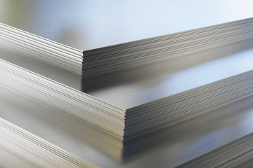



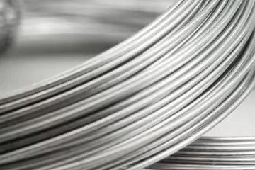
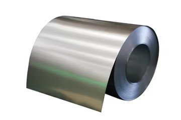












Titanium Foil Specification & Metallurgy Guide: 20-High Sendzimir Tolerances, Vacuum Annealing & Slitting Geometry
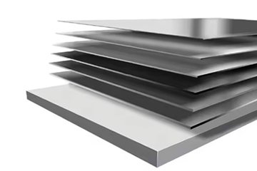
Precision titanium foil spans nominal thicknesses from 0.005 mm (5 μm) to 0.50 mm (500 μm), occupying an engineering domain where conventional flat-rolling assumptions cease to apply. The mechanical and crystallographic properties of unalloyed and alpha-beta titanium alloys change drastically when raw stock is reduced down to dimensions comparable to the metal's grain structure. Standard commercial rolling mills cannot maintain continuous transverse gauge uniformity at these levels. Producing flat, pinhole-free strip requires dedicated cold rolling on 20-High Sendzimir cluster mills equipped with multi-zone shape-control actuators and automated radiometric gauge sensors.
Procuring precision Titanium Foil requires a strict specification methodology that controls for thickness variability, interstitial purity, internal crystallographic texture, and edge geometry. When material thickness drops below 0.10 mm, minor variations in interstitial elements—specifically oxygen and hydrogen—directly alter work hardening rates, causing localized necking during deep micro-stamping or catastrophic micro-cracking in hydroforming dies. A complete purchase specification must establish unambiguous boundaries for chemical mass fractions per ASTM B265, sub-micron surface topography parameters (Ra, Rz), and crystallographic grain sizing evaluated under ASTM E112.
Engineers specifying thin-gauge titanium must account for how rolling direction affects deformation mechanics. Due to its hexagonal close-packed (HCP) alpha-phase crystal lattice, cold-rolled titanium develops a pronounced basal texture during reductions exceeding 30%. This anisotropy influences the Lankford parameter (r-value), directly altering the material's limiting draw ratio (LDR) and susceptibility to shear band localization. By integrating advanced vacuum metallurgical processing, controlled intermediate recrystallization annealing, and precision rotary slitting, designers can leverage titanium's corrosion resistance and high specific strength while avoiding the classic production failures typical of ultra-thin foil conversion.
Dimensional Classifications & The ASTM B265 Sub-0.40 mm Specification Gap
A persistent challenge in industrial procurement is the structural specification gap within the baseline standard, ASTM B265 (Standard Specification for Titanium and Titanium Alloy Strip, Sheet, and Plate). ASTM B265 formally classifies all flat-rolled product below 4.76 mm (0.1875 in.) in thickness and under 610 mm (24 in.) in width as "Strip," while product wider than 610 mm is categorized as "Sheet." However, its standard thickness tolerance tables cease at 0.40 mm (0.016 in.). When a buyer places a purchase order for 0.025 mm, 0.050 mm, or 0.100 mm titanium flat product citing solely "per ASTM B265," the critical parameters of thickness tolerance, allowable transverse gauge crown, and edge slit burr are left undefined by the standard.
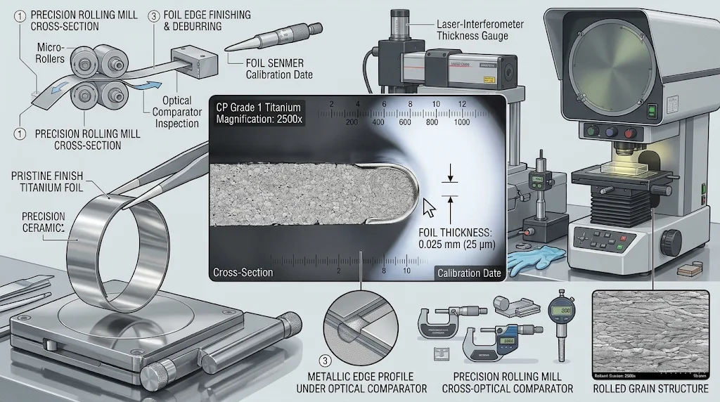
To establish contractual and technical clarity, precision mills and advanced fabricators utilize a functional three-tier dimensional hierarchy. Material measuring 0.005 mm to 0.150 mm is designated as Titanium Foil; thicknesses from 0.150 mm to 0.500 mm are designated as Micro-Strip (or ultra-thin strip); and gauges exceeding 0.500 mm transition into standard Titanium Strip and Titanium Sheet. National standards such as China's GB/T 3622 formally define foil as material with nominal thickness ≤ 0.10 mm, but industrial processing limits mandate that any product rolled beneath 0.40 mm requires explicit bilateral tolerance agreements between the mill and customer.
Failure to close this tolerance gap results in substantial yield loss during secondary fabrication. If a procurement contract lacks explicit thickness tolerances, an ASTM B265 compliant mill could legally supply a 0.050 mm strip with the ±0.050 mm tolerance band associated with the thinnest listed category (0.40 mm). This creates the potential for zero minimum thickness or a 100% overweight scenario. In high-precision applications like proton exchange membrane (PEM) electrolyzer flow fields or acoustic diaphragms, an undocumented gauge drift of just 0.005 mm alters diaphragm resonance frequencies by over 20% or causes channel punching through bipolar flow plates during progressive die stamping.
| Classification | Thickness Range (mm) | Standard Rolling Technology | Applicable Standards | Default Standard Tolerance Risk |
|---|---|---|---|---|
| Ultra-Thin Foil | 0.005 to 0.050 | 20-High Sendzimir Cluster Mill | GB/T 3622, Internal Mill Spec | Uncovered by ASTM B265; thickness tolerances undefined if not agreed. |
| Precision Foil | 0.051 to 0.150 | 20-High / 12-High Cluster Mill | GB/T 3622, ASTM B265 (Chemistry Only) | ASTM B265 lacks mechanical testing and thickness tables below 0.40 mm. |
| Micro-Strip | 0.151 to 0.400 | 4-High Reversing / Sendzimir Mill | ASTM B265, AMS 4902, GB/T 3622 | ASTM B265 thickness tolerances apply only down to 0.40 mm limits. |
| Standard Strip | 0.401 to 4.760 | 4-High Continuous / Tandem Mill | ASTM B265, ASME SB265, AMS 4911 | Fully covered by ASTM standard tables for thickness, width, and camber. |
20-High Sendzimir Mill Precision Thickness & Width Tolerance Matrix (0.005 mm – 0.50 mm)
Rolling unalloyed titanium and high-strength titanium alloys down to micron gauges demands extreme roll-gap rigidity. Conventional 2-high or 4-high rolling mills experience significant roll deflection, roll flattening, and housing stretch under the high specific roll-separating forces required to cold-reduce work-hardened titanium. China Titanium Factory deploys 20-High Sendzimir cluster cold rolling mills. In a Sendzimir mill, two small-diameter work rolls (typically 10 mm to 30 mm in diameter, made of tungsten carbide or high-alloy powder metallurgical tool steel) are directly supported by four first-intermediate rolls, six second-intermediate rolls, and eight continuous backing bearing assemblies mounted within a rigid one-piece cast steel housing.
The small contact diameter of the Sendzimir work roll significantly minimizes the total contact area between roll and foil. This drastically cuts the required roll-separating force and reduces elastic roll flattening, allowing high per-pass reduction ratios without edge spalling or center blowout. Modern Sendzimir mills use closed-loop Automatic Gauge Control (AGC) driven by high-speed non-contact X-ray or isotopic radiometers placed directly at the entry and exit roll bites. These sensors capture gauge deviations at millisecond intervals, automatically actuating hydraulic screw-down cylinders and adjusting the internal crown profile via the mill's eccentric saddle assemblies ("As-U-Roll" crown adjustment).
| Nominal Thickness Band (mm) | Standard Width Band (mm) | ASTM B265 Commercial Tolerance (mm) | CTF Sendzimir Precision AGC Tolerance (mm) | Rotary Slit Width Tolerance (mm) |
|---|---|---|---|---|
| 0.005 to 0.010 | 2.0 to 150.0 | Not Defined | ±0.0008 | ±0.03 |
| 0.011 to 0.030 | 2.0 to 300.0 | Not Defined | ±0.0012 | ±0.04 |
| 0.031 to 0.050 | 2.0 to 450.0 | Not Defined | ±0.0015 | ±0.05 |
| 0.051 to 0.100 | 5.0 to 650.0 | Not Defined | ±0.0020 | ±0.05 |
| 0.101 to 0.250 | 5.0 to 650.0 | ±0.0300 (extrapolated) | ±0.0035 | ±0.08 |
| 0.251 to 0.500 | 5.0 to 650.0 | ±0.0400 (per Table 3, B265) | ±0.0050 | ±0.10 |
Transverse gauge uniformity across the entire coil width is maintained by profiling the intermediate rolls. Because titanium displays a high ratio of yield strength to elastic modulus (E = 105 GPa to 115 GPa for unalloyed alpha titanium), improper crown control results in severe cross-sectional profile anomalies, commonly manifest as edge pinch or center belly. The intermediate lateral shifting mechanism on our 20-High Sendzimir clusters permits continuous tapering adjustments across the edge drop region (the initial 15 mm to 25 mm from the strip edge), ensuring the transverse thickness deviation stays within 1.0% of the nominal foil center gauge.
Cold Rolling Metallurgy, Work Hardening & High-Vacuum Bright Annealing
Alpha-phase titanium possesses a Hexagonal Close-Packed (HCP) crystal lattice with an axial ratio c/a of approximately 1.587—well below the ideal close-packed ratio of 1.633. Because of this crystallographic geometry, room-temperature plastic deformation cannot occur through basal slip {0001}<1120> alone, as this system provides only two independent slip directions. To satisfy the von Mises criterion requiring five independent slip systems for uniform plastic deformation, cold reduction relies heavily on prismatic slip {1010}<1120>, first-order pyramidal slip {1011}<1120>, and extensive mechanical twinning along the {1012}, {1121}, and {1122} planes.
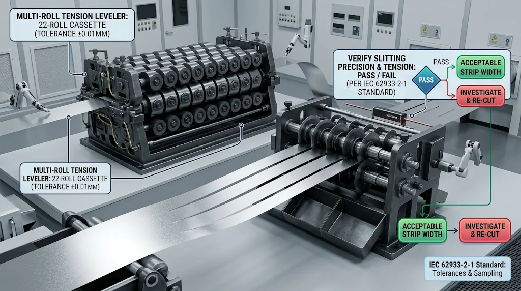
Even if an annealed foil appears visually flat while under line tension, it can harbor severe internal residual stress gradients. When subjected to photochemical etching or UV laser micro-cutting, chemical removal of material alters the internal mechanical equilibrium. The relief mechanism follows a clear physical chain: unbalanced residual stress (Δσresidual) produces an internal bending moment, leading to spontaneous camber warping. Etched components like micro-leadframes, transmission electron microscopy (TEM) aperture grids, or pacemaker battery cathode tabs then warp uncontrollably out of flat, jamming automated pick-and-place lines.
Eliminating this latent distortion requires continuous tension-leveling operations. The uncoiled foil passes through a multi-roll leveler cassette consisting of small-diameter (7 mm to 15 mm) work rolls backed by stiff support rolls under high tension. By cycling the material through precisely calculated reverse plastic bending under pure tension, the elastic-plastic strain history across the entire strip cross-section is equalized. This process reduces latent internal residual stress to negligible levels and locks in final global flatness within 5 to 10 I-units (equivalent to wave heights under 0.8 mm over a 1,000 mm wave length).
Rotary Shear Slitting Burr Limits, Coil Camber & Optical Pinhole Inspection Criteria
Downstream production speed and die life depend directly on edge slitting quality. Ultra-thin titanium foil cannot be processed using standard low-tolerance steel shears, which cause rough ductile tearing, high edge rollover, and massive burrs. Precision coil slitting relies on solid tungsten carbide rotary shear knives ground to a mirror surface (Ra ≤ 0.05 μm) and mounted on high-precision arbor shafts running in ultra-precision class P4 spindle bearings. Axial arbor runout must be held strictly under ±0.001 mm (1 μm).
The knife clearance profile is critical. The horizontal blade clearance is maintained at 3% to 5% of the nominal foil thickness, while blade overlap (vertical penetration) is adjusted to zero or a slight negative overlap (-0.01 mm to -0.03 mm) depending on temper. Controlled shear slitting ensures the edge burr height does not exceed 3% of the nominal thickness (for example, maximum burr height ≤ 0.75 μm on a 0.025 mm foil). Clean edge geometries prevent burr detachment during automated high-speed progressive die stamping, protecting micro-punches from premature chipping and eliminating loose metallic debris that causes short-circuits in high-density electronics.
| Foil Thickness (mm) | Maximum Burr Height (μm) | Max Lateral Camber (mm/1000mm) | Flatness Index (I-Units) | Optical Pinhole Permissibility |
|---|---|---|---|---|
| 0.005 to 0.015 | ≤ 0.5 μm | ≤ 0.50 mm | ≤ 5 I-Units | Zero > 10 μm per m² (10,000 lux transillumination) |
| 0.016 to 0.050 | ≤ 1.0 μm | ≤ 0.50 mm | ≤ 5 I-Units | Zero > 10 μm per m² (10,000 lux transillumination) |
| 0.051 to 0.100 | ≤ 2.5 μm | ≤ 0.80 mm | ≤ 8 I-Units | Zero through-thickness voids permitted |
| 0.101 to 0.250 | ≤ 5.0 μm | ≤ 1.00 mm | ≤ 10 I-Units | Zero through-thickness voids permitted |
| 0.251 to 0.500 | ≤ 8.0 μm | ≤ 1.20 mm | ≤ 10 I-Units | Zero through-thickness voids permitted |
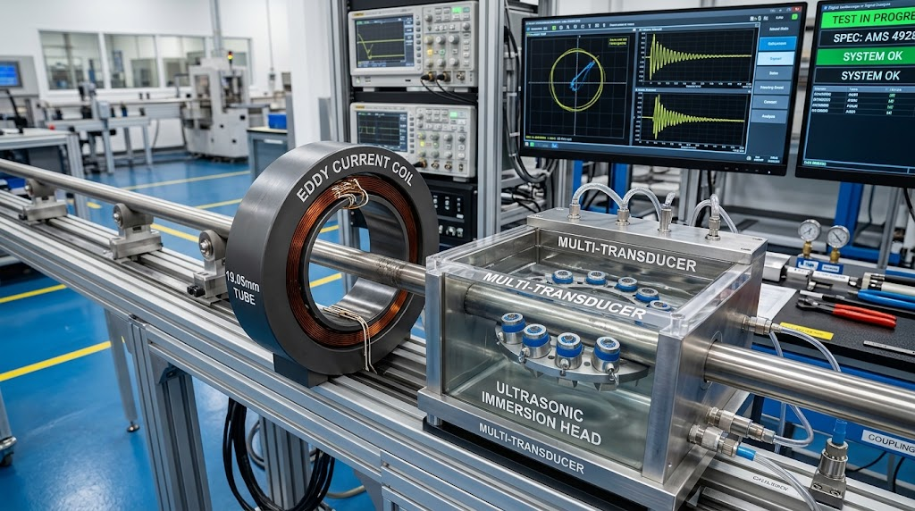
Coil camber—defined as the lateral deviation of a slit edge from a true straight line over a fixed measurement length—must not exceed 0.50 mm over a 1,000 mm span. Excessive camber causes the slit strip to walk laterally within progressive die stock guides, creating misaligned punch strikes. Furthermore, for vacuum-tight hermetic applications (such as chemical rupture discs, aerospace acoustic isolators, and medical implants), coils are 100% verified via continuous inline 10,000 lux optical transillumination testing. High-intensity LED arrays illuminate the undersurface of the running foil while high-resolution CMOS line-scan cameras detect optical transmission on the upper surface, guaranteeing zero pinholes larger than 10 μm per square meter.
Grade Selection, Chemical Composition & Mechanical Thresholds by Application
Selecting the optimal titanium alloy grade requires balancing formability against mechanical yield strength and environmental corrosion resistance. Unalloyed Commercially Pure (CP) titanium grades—Grade 1, Grade 2, and Grade 4—are distinguished primarily by their allowable interstitial oxygen and iron content. Higher interstitial contents systematically raise yield strength while lowering tensile elongation and limiting formability.
CP Grade 1 (UNS R50250) features the lowest oxygen ceiling (O ≤ 0.18 wt%) and lowest iron limit (Fe ≤ 0.20 wt%). It offers maximum ductility (elongation ≥ 24% at > 0.1 mm), making it the primary choice for deep-drawn micro-components, PEM fuel cell/electrolyzer bipolar plates, and complex folded aerospace heat exchanger fins. CP Grade 2 (UNS R50400) strikes an ideal balance between moderate strength (Rm ≥ 345 MPa) and corrosion resistance, serving as the industrial standard for chemical processing burst discs, high-frequency acoustic tweeter domes, and marine micro-filters.
| Grade & UNS | Carbon (C) | Iron (Fe) | Nitrogen (N) | Hydrogen (H) | Oxygen (O) | Aluminum (Al) | Vanadium (V) | Titanium (Ti) |
|---|---|---|---|---|---|---|---|---|
| CP Gr 1 (R50250) | 0.08 | 0.20 | 0.03 | 0.0125 | 0.18 | — | — | Balance |
| CP Gr 2 (R50400) | 0.08 | 0.30 | 0.03 | 0.0125 | 0.25 | — | — | Balance |
| CP Gr 4 (R50700) | 0.08 | 0.50 | 0.05 | 0.0125 | 0.40 | — | — | Balance |
| Gr 5 Ti-6Al-4V (R56400) | 0.08 | 0.40 | 0.05 | 0.0125 | 0.20 | 5.50–6.75 | 3.50–4.50 | Balance |
| Gr 23 ELI (R56401) | 0.08 | 0.25 | 0.03 | 0.0125 | 0.13 | 5.50–6.50 | 3.50–4.50 | Balance |
| Beta-21S (R58210) | 0.05 | 0.40 | 0.05 | 0.0150 | 0.17 | 2.50–3.50 | — | Balance* |
*Beta-21S contains deliberate alloying elements: 14.0–16.0% Mo, 2.7–3.3% Nb, 0.15–0.25% Si.
| Grade & Condition | Yield Strength Rp0.2 (MPa) | Tensile Strength Rm (MPa) | Elongation A50mm (%) | Microhardness (HV0.2) | Min Bend Radius (180°) |
|---|---|---|---|---|---|
| CP Gr 1 (Annealed) | 170 – 240 | 240 – 340 | ≥ 20% | 120 – 145 | 0.5 t |
| CP Gr 2 (Annealed) | 275 – 380 | 345 – 480 | ≥ 18% | 150 – 185 | 1.0 t |
| CP Gr 4 (Annealed) | 480 – 620 | 550 – 720 | ≥ 12% | 210 – 250 | 1.5 t |
| Gr 5 / Gr 23 ELI | 790 – 910 | 895 – 1050 | ≥ 6% | 310 – 360 | 4.5 t to 6.0 t |
| Gr 1 (Full Hard - TR) | ≥ 550 | ≥ 650 | ≤ 3% | 210 – 240 | 3.0 t (W-bend) |
| Beta-21S (Strip Anneal) | 760 – 880 | 820 – 950 | ≥ 12% | 280 – 320 | 2.0 t |
For applications demanding high strength-to-weight ratios under elevated temperatures (such as aerospace structural honeycomb cores and engine thermal shields), alloy foils like Ti-6Al-4V Grade 5, Grade 23 ELI (Titanium Metal Grades), and metastable Beta alloys (Beta-21S, Ti-15-3-3-3) are preferred. Beta alloys offer a Body-Centered Cubic (BCC) crystal structure that provides higher cold rollability and strip ductility than Grade 5, while maintaining precipitation-hardenability up to tensile strengths exceeding 1,250 MPa post-aging.
Operational Boundaries, Chemical Taboos & Failure Prevention in Ultra-Thin Foil
Designing with ultra-thin titanium foil requires specialized failure prevention strategies that differ fundamentally from structural plate engineering. Because of its microscopic thickness, material that performs reliably at thicker gauges can experience rapid operational failure if environmental, physical, and crystallographic boundaries are overlooked.
1. Surface Pyrophoricity and Ignition Risks: Thin titanium foil (< 0.025 mm / 25 μm) exhibits an exceptionally high surface-area-to-volume ratio. Solid titanium burns with an intense, self-sustaining exothermic reaction (flame temperatures exceed 2,800°C) if ignited. Never use oxygen as an assist gas during UV or fiber laser micro-cutting of ultra-thin foil; dry nitrogen or high-purity argon assist gas must be used exclusively. Furthermore, in chemical systems, exposure to gaseous oxygen pressures above 350 kPa (50 psi) at ambient temperatures can trigger autoignition if the foil experiences high-velocity mechanical tearing, friction, or static discharge.
2. Chemical Environment Corrosion Limits: Although passivated by a stable titanium dioxide (TiO2) film, ultra-thin foils lack the mass thickness needed to withstand even minor uniform corrosion rates. Common corrosive boundaries include:
Dry Chlorine Gas Taboo: Titanium requires a minimum of 1.5% moisture (H2O) by weight at room temperature to maintain its passivating oxide layer. In dry chlorine gas, an aggressive, highly exothermic reaction initiates instantly, destroying a 0.05 mm foil in seconds.
Red Fuming Nitric Acid: Exposure to anhydrous red fuming nitric acid creates severe risk of intergranular stress corrosion cracking (SCC) and rapid pyrophoric detonations.
Reducing Acids: Hydrofluoric, hydrochloric, and sulfuric acids attack titanium rapidly. A nominal corrosion rate of 0.05 mm/year—negligible on a 20 mm plate—will dissolve a 0.025 mm foil in six months.
3. The Microstructural Size Effect (t/d Ratio Boundary): As foil thickness (t) approaches the average grain diameter (d), classic continuum mechanics models break down. When the thickness-to-grain-diameter ratio falls below five (t/d < 5), the foil can no longer be modeled as an isotropic polycrystalline material. Deformation becomes dominated by the crystallographic orientation of individual grains spanning the entire foil thickness. Consequently, tensile elongation (A50) drops rapidly from > 22% down to single digits (3% to 6%), as dislocations cross individual grains and emerge at free surfaces without generating back-stress work hardening. To maintain deep-drawing ductility, the mill must keep recrystallized grain sizes at ASTM No. 10 or finer (d < 11 μm), ensuring a t/d ratio > 5 is maintained across sub-0.05 mm foils.
4. High Springback and Severe Die Galling: In high-strength alloys such as cold-rolled Grade 5 or Grade 4, the ratio of yield strength to elastic modulus (Rp0.2/E) is exceptionally high. During cold forming, substantial elastic energy is recovered upon unloading, leading to extensive springback (often 15° to 30° on a 90° bend). Additionally, clean titanium displays severe solid-state adhesion (galling) against tool steels. High-speed progressive stamping tooling requires diamond-like carbon (DLC) or titanium carbo-nitride (TiCN) PVD coatings, paired with thin-film fluoropolymer lubricants or dry soap drawing compounds.
Cleanroom Degreasing, Anti-Telescoping Coil Packaging & Purchase Order Template
Residual cold-rolling lubricants (typically synthetic esters or mineral oils) cause critical defects if left on the foil. If coiled strip with rolling oil residues enters high-vacuum annealing furnaces, the oil cracks into elemental carbon and hydrogen. This process irreversibly carburizes the foil surface, forming hard, abrasive titanium carbides (TiC) that ruin ductility and prevent reliable vacuum brazing, spot welding, or surface coating. China Titanium Factory passes all slit coils through multi-stage inline ultrasonic hydrocarbon vapor degreasers followed by heated deionized (DI) water cascading rinses and filtered clean-air drying, guaranteeing absolute surface cleanliness (surface energy > 44 mN/m, zero carbonaceous residues per ASTM F21).
Preserving coil geometry during global transit requires anti-telescoping packaging protocols. Slit foil coils are tightly wound onto high-strength, non-outgassing ABS, aluminum, or phenolic cores with standard inner diameters (76 mm / 3 in., 152 mm / 6 in., or 200 mm / 8 in.). The coil strip is interleaved with acid-free, sulfur-free neutral pH tissue paper to eliminate friction scratches. Coils are individually hermetically sealed in multi-layer aluminum-barrier mylar vacuum bags containing active silica gel desiccant packs, then suspended via horizontal through-core support mandrels inside ISPM 15 heat-treated export wooden cases. Suspending the coil eliminates resting weight on the strip edges, preventing edge denting, coil ovality, and lateral telescoping.
Industrial Purchase Order (PO) Engineering Specification Template
To eliminate ambiguity when specifying precision titanium foil, paste the following structured specification block directly into your ERP/PO documentation:
--------------------------------------------------------------------------------
1. MATERIAL GRADE: Titanium CP Grade 1 (UNS R50250) / ASTM B265, ASTM F67, AMS 4902.
2. MELT PROCESS: 100% Double or Triple Vacuum Arc Remelted (VAR) Ingot Traceability.
3. NOMINAL DIMENSIONS: Thickness: 0.050 mm (±0.0015 mm) | Width: 150.0 mm (±0.05 mm) | Coil ID: 152 mm (Phenolic Core).
4. TRANSVERSE PROFILE: Center-to-Edge Crown < 0.0010 mm; Edge Drop Zone Width < 15 mm.
5. TEMPER & HEAT TREATMENT: Fully Recrystallized Vacuum Annealed (M Condition) at vacuum level ≤ 1 × 10⁻³ Pa.
6. HYDROGEN / INTERSTITIAL CEILINGS: H ≤ 0.0050% (50 ppm) | O ≤ 0.15% | Fe ≤ 0.12% (Finished Foil Test).
7. MICROSTRUCTURE: Equiaxed Alpha Grains; ASTM E112 Grain Size Number ≥ 9.5 (Mean grain diameter ≤ 14 μm); Zero Alpha-Case.
8. MECHANICAL PROPERTIES: Rp0.2: 170–220 MPa | Rm: 240–320 MPa | A50mm: ≥ 22% | IE Cupping: ≥ 7.0 mm (ISO 20482).
9. SURFACE QUALITY & CLEANLINESS: Ra ≤ 0.10 μm (Bright Finish) | Cleanroom Ultrasonically Degreased (Zero carbonaceous residue).
10. SLITTING GEOMETRY & FLATNESS: Burr Height ≤ 1.5 μm (≤ 3% of gauge) | Lateral Camber ≤ 0.50 mm/1000 mm | Flatness ≤ 5 I-Units.
11. DEFECT FREQUENCY: 100% Continuous 10,000 Lux Optical Transillumination Tested; Zero pinholes > 10 μm/m².
12. CERTIFICATION & TRACEABILITY: Certified EN 10204 3.1 Inspection Certificate with heat/lot chemistry, tensile, and microstructure micrographs.
13. PACKAGING: Core-suspended, interleaved with sulfur-free tissue, sealed in vacuum mylar barrier bag, packed in ISPM 15 wooden crate.
Related Technical Specifications & Material Grade Hub
| Alloy Grade | Form Category | Standard Cross-Reference | Key Engineering Characteristics | Primary Industrial Application |
|---|---|---|---|---|
| CP Grade 1 | Titanium Foil | ASTM B265, ASTM F67 | Maximum drawability, lowest interstitials, high thermal conductivity. | PEM electrolyzers, acoustic tweeters, battery substrates. |
| CP Grade 2 | Titanium Strip | ASTM B265, AMS 4902 | Moderate yield strength, exceptional resistance to oxidizing media. | Chemical burst diaphragms, heat exchangers, marine sensors. |
| CP Grade 4 | Titanium Sheet | ASTM B265, ASTM F67 | High unalloyed strength (Rm ≥ 550 MPa), structural rigidity. | Medical implant shells, high-pressure rupture membranes. |
| Ti-6Al-4V Gr 5 | Titanium Metal Grades | ASTM B265, AMS 4911 | Extreme specific strength, high fatigue endurance limit. | Aerospace honeycomb core, laser-sintered micro-structures. |
| Custom Conversion | Custom Fabrication Service | ISO 9001, AS9100D | Precision rotary slitting, leveling, and custom photochemical etching. | Complex stamped drawn parts, precision etched sensor arrays. |
Technical Verification FAQ & Engineering Consultation
Why does elongation (A50) drop on tensile tests of < 0.05 mm foil, and when should microhardness HV or Erichsen cupping be used instead?
Tensile testing ultra-thin foil per ASTM E8/E8M faces inherent specimen geometry limitations. Below 0.05 mm, specimen edge finish artifacts, micro-burrs from gauge cutting, and minor alignment errors in gripping jaws create localized stress concentrations that trigger premature necking. This reduces measured elongation (A50) well below the material's true physical ductility. Therefore, for foils under 0.050 mm, mechanical ductility and formability are accurately evaluated using the Erichsen Cupping Test per ISO 20482 (measuring the depth of spherical dome impression at crack initiation, requiring IE ≥ 6.5 mm to 7.5 mm for annealed Grade 1) paired with Vickers Microhardness (HV0.2) per ASTM E384 to track temper without tensile notch sensitivity errors.
How do you prevent coil edge welding (sticking) during batch vacuum annealing of 0.01 mm foil?
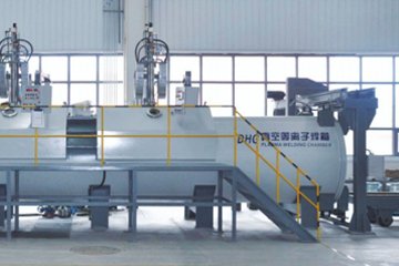
During high-vacuum batch annealing (≤ 1 × 10⁻³ Pa at 600°C), ultra-clean titanium surfaces experience solid-state diffusion bonding (sticking or thermal welding) at coil edges under winding contact pressures. Because vacuum eliminates the natural oxide barrier, touching laps can weld together, tearing thin 0.01 mm foil during subsequent unwinding. China Titanium Factory prevents this through dual countermeasures: (1) Applying continuous low-tension rewinding prior to annealing, using segmented dancer rolls that regulate coil packing density to strict radial pressure targets; and (2) Optional pre-oxidation treatments that maintain an engineered mono-molecular TiO2 barrier layer, or utilizing loose continuous reel-to-reel strand vacuum annealing furnaces where the foil passes through the heating zone unsupported without lap-to-lap contact.
Can Ti-6Al-4V Grade 5 foil be cold-rolled to 0.01 mm, or is pack-rolling / Beta-Ti substitution required?
Due to its high yield strength (Rp0.2 > 830 MPa) and limited slip systems, Ti-6Al-4V Grade 5 work hardens too rapidly to be cold-rolled down to 0.01 mm (10 μm) on standard industrial cluster mills. Cold rolling of Grade 5 reaches a mechanical processing limit around 0.050 mm. Gauges thinner than 0.050 mm require either pack-rolling—where the titanium foil is encased within sacrificial low-carbon steel or stainless steel sheets and hot-rolled at 750°C–850°C followed by acid dissolution of the cladding—or substituting Grade 5 with a cold-rollable metastable beta alloy such as Beta-21S (Ti-15Mo-3Nb-3Al-0.2Si). Beta-21S is cold-rolled directly on Sendzimir mills down to 0.015 mm, then aged to match or exceed Grade 5 tensile strength.
What surface contact resistance (ICR) and roughness parameters are required for PEM fuel cell bipolar plate foil?
For PEM fuel cell and electrolyzer bipolar plates, interfacial contact resistance (ICR) between the titanium foil and carbon gas diffusion layer (GDL) directly influences stack efficiency. Native oxide layers on titanium yield high ICR values (> 100 mΩ·cm² under 1.4 MPa compaction pressure). The foil must possess an initial surface roughness of Ra ≤ 0.15 μm to ensure uniform current distribution, followed by thin-film platinum-group metal (Pt, Ir) or conductive titanium nitride (TiN/CrN) PVD coating applied directly onto the vacuum-annealed strip. Clean high-vacuum annealing guarantees an initial base ICR < 20 mΩ·cm² without non-conductive carbon contamination, maintaining long-term corrosion resistance in acidic anode environments (pH 2–3) at potentials up to 2.0 V vs. SHE.
Technical Consultation & Mill Test Certificate (MTC) Requests
Procuring ultra-thin precision titanium foil requires verification of raw material provenance, furnace vacuum levels, and slit edge geometry. China Titanium Factory provides complete engineering and technical validation for high-reliability manufacturing programs:
Step 1: Submit target thickness, width, coil dimensional constraints, and operational operating parameters via 2D/3D DWG or STEP files.
Step 2: Receive a comprehensive 12-hour DFM feasibility report covering roll-reduction schedules, slitting tolerances, and certified EN 10204 3.1 MTC inspection sample dossiers.
Step 3: Schedule a direct technical consultation with our Chief Cold Rolling Metallurgist to lock in custom hardness temper, surface roughness, and packaging specifications.