



















Medical Implant Titanium CNC Machining: ASTM F136 Grade 23 Metallurgy, Swiss Turning Dynamics & ISO 13485 Traceability
Precision manufacturing of implantable medical devices demands rigorous control over material purity, mechanical integrity, and microstructural uniformity. Structural orthopedic, spinal, and dental prosthetics face cyclic biological stresses in human physiological environments. Meeting these performance demands requires bridging the gap between metallurgy and multi-axis subtractive production. Processing biomedical alloys through Titanium CNC Machining centers requires strict adherence to international regulatory frameworks, specifically ISO 13485 quality systems and ASTM biocompatibility metrics.
Components engineered from medical-grade Titanium Metal Grades such as ASTM F136 Grade 23 Extra Low Interstitial (ELI) provide a superior strength-to-density ratio compared to 316L stainless steel and cobalt-chromium-molybdenum (CoCrMo) alloys. Grade 23 titanium exhibits an elastic modulus of approximately 110 GPa. This closer mechanical match to human cortical bone (10–30 GPa) significantly mitigates clinical stress shielding and subsequent periprosthetic bone resorption. Achieving these biological advantages requires eliminating interstitial contamination during raw material synthesis and preventing thermal damage during machining.
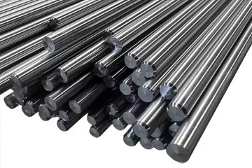
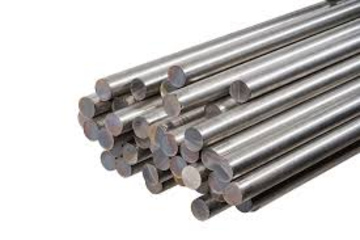
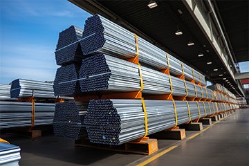
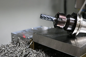
Executing Swiss turning and 5-axis micro-milling on medical-grade titanium requires distinct process dynamics compared to standard commercial manufacturing. Precision components require centerless ground Titanium Rod stock with tight diametrical tolerances (ISO h6 or h5) to stabilize high-speed rotation within Swiss guide bushings. Because titanium's thermal conductivity is extremely low (6.7 W/m·K at 20°C), up to 80% of cutting heat concentrates directly at the cutting edge. This concentration risks localized microstructural alteration, tool wear, and surface strain hardening. Ensuring zero-defect production requires synchronizing tool coatings, using high-pressure coolant (70 to 140 bar), applying automated non-contact optical metrology, and maintaining complete Device History Record (DHR) tracking.
Implantable Titanium Metallurgy & Upstream Bar Stock Pedigree
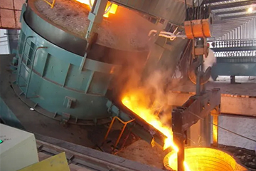
The manufacturing quality of an implantable medical device is determined long before raw stock reaches a CNC machine spindle. Standard industrial titanium, governed by specifications like ASTM B348, accommodates broad chemical variations and inclusion tolerances designed for chemical tanks, heat exchangers, and marine fittings. In contrast, medical-grade wrought titanium processed under ISO 5832-3 and ASTM F136 requires tighter metallurgical control. Small non-metallic inclusions, excessive interstitial gas concentrations, or segregation banding within raw stock can cause catastrophic in vivo failures under cyclic multiaxial fatigue loads.
During secondary processing, raw titanium sponge must undergo rigorous primary consolidation to ensure chemical homogeneity. Residual microscopic defects—specifically Type I high-interstitial hard-alpha inclusions (nitrogen/oxygen-enriched areas with elevated melting points) and high-density inclusions (HDI) from detached tungsten carbide tool tips or fragmented master alloy particles—act as primary fatigue crack nucleation sites. When subjected to billions of loading cycles within a hip stem or spinal stabilization construct, unrefined alloy defects lead to mechanical failure well below theoretical endurance limits.
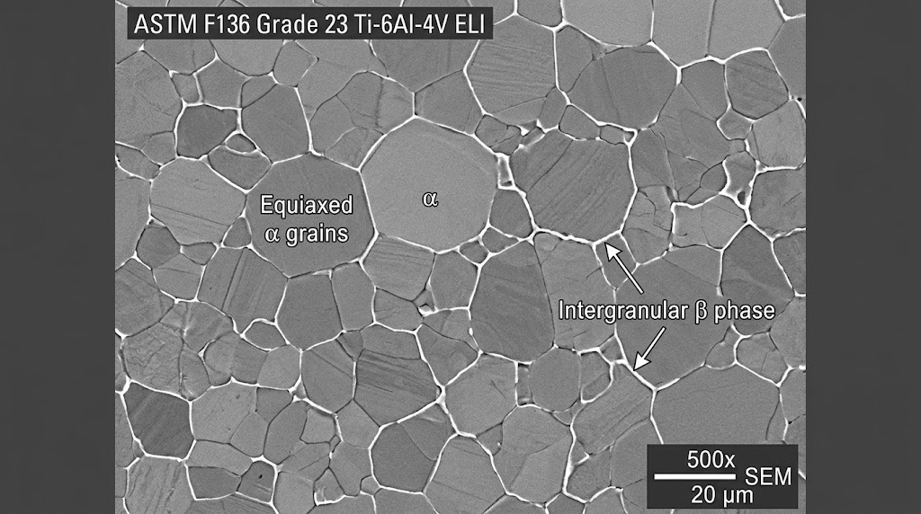
Thermomechanical processing of medical bar stock requires tight temperature control during forging and rolling stages. Processing temperature relative to the alloy's beta-transus point (Tβ ≈ 975°C to 995°C for Ti-6Al-4V ELI) defines the final distribution of alpha (hexagonal close-packed) and beta (body-centered cubic) phases. Medical-grade stock requires finish-working within the alpha-beta phase field, followed by recrystallization annealing. This thermomechanical pathway yields an equiaxed, globularized alpha-beta microstructure. This structure provides the optimal balance of tensile strength, ductility, notch sensitivity, and high-cycle fatigue resistance required for long-term surgical implantation.
ASTM F136 Grade 23 (Ti-6Al-4V ELI) vs. Standard Grade 5 Interstitial Control
The primary metallurgical difference between ASTM F136 Grade 23 and industrial ASTM B348 Grade 5 lies in the precise limitation of interstitial elements: oxygen, nitrogen, hydrogen, and carbon, along with substitutional iron. Interstitial elements occupy octahedral and tetrahedral spaces within the hexagonal close-packed (HCP) alpha titanium crystal lattice. Dissolved oxygen and nitrogen restrict slip systems, preventing dislocation movement. While this interstitial solute strengthening increases ultimate tensile yield strength, it reduces fracture toughness and critical crack propagation thresholds.
| Parameter / Elemental Weight Limit | ASTM B348 Grade 5 (Industrial) | ASTM F136 Grade 23 ELI (Medical) | Engineering Significance for Medical Devices |
|---|---|---|---|
| Oxygen (O), wt% max | ≤ 0.20% | ≤ 0.13% | Prevents lattice embrittlement; maximizes KIC fracture toughness. |
| Iron (Fe), wt% max | ≤ 0.40% | ≤ 0.25% | Eliminates beta-fleck segregation; prevents galvanic micro-cells. |
| Nitrogen (N), wt% max | ≤ 0.05% | ≤ 0.03% | Suppresses hard-alpha inclusion formation and ductility reduction. |
| Carbon (C), wt% max | ≤ 0.08% | ≤ 0.08% | Prevents brittle titanium carbide (TiC) precipitation at grain boundaries. |
| Hydrogen (H), wt% max | ≤ 0.015% (150 ppm) | ≤ 0.012% (120 ppm) | Precludes hydride precipitation and slow strain rate embrittlement. |
| Min. Tensile Strength (Rm) | ≥ 895 MPa (130 ksi) | ≥ 860 MPa (125 ksi) | Controlled reduction accommodates superior dynamic plastic reserve. |
| Min. Yield Strength (Rp0.2) | ≥ 828 MPa (120 ksi) | ≥ 795 MPa (115 ksi) | High load-bearing capacity without sudden catastrophic rupture. |
| Min. Elongation (A4) | ≥ 10% | ≥ 10% | Guarantees cold-forming ductile capacity during intraoperative contouring. |
| Min. Reduction of Area (Z) | ≥ 25% | ≥ 25% | Essential measure of local triaxial ductility under complex multiaxial strain. |
Limiting interstitial oxygen to a strict ceiling of ≤ 0.13 wt% in Grade 23 ELI improves performance in load-bearing implants, such as polyaxial pedicle screws, intramedullary rods, and spinal fusion cages. Lower oxygen content directly elevates plane-strain fracture toughness (KIC). Standard Grade 5 titanium exhibits KIC values between 40 and 60 MPa·m1/2, whereas certified ASTM F136 Grade 23 regularly achieves 75 to 105 MPa·m1/2. This increased crack propagation resistance prevents catastrophic device failure when minor surface notches are introduced during surgical handling or dynamic fretting against modular locking assemblies.
Restricting iron content to Fe ≤ 0.25 wt% prevents the formation of "beta-flecks." Iron acts as a strong beta-phase stabilizer. During ingot solidification, positive partition coefficients can cause localized iron segregation, producing coarse beta grains with anomalous transformation behavior. These macro-segregations can alter local mechanical properties, create non-uniform electrochemical potentials that degrade localized corrosion resistance, and cause micro-cracking during deep-hole drilling or complex profiling on CNC machines.
ASTM F67 Cold-Worked CP Titanium (Grades 2 & 4) for Dental & Craniofacial Implants
Commercially pure (CP) titanium materials governed by ASTM F67 and ISO 5832-2 are unalloyed alpha formulations configured across four distinct grades (Grades 1 through 4). In these pure grades, mechanical yield and ultimate tensile strengths are controlled by calibrated additions of interstitial oxygen (ranging from ≤ 0.18 wt% in Grade 1 to ≤ 0.40 wt% in Grade 4) and trace iron, rather than through aluminum or vanadium additions. Eliminating alloying elements removes the potential risk of long-term systemic toxic ion release. This makes CP titanium well suited for endosseous dental implants, maxillo-facial osteosynthesis hardware, and thin cranial repair meshes.
Annealed ASTM F67 Grade 4 titanium provides an ultimate tensile strength of approximately 550 MPa, which can be insufficient for narrow-diameter dental implant fixtures subjected to high masticatory shear forces. To overcome this limitation without compromising biological safety, raw material suppliers apply precise cold-working protocols (30% to 50% rotary swaging or cold-drawing). This plastic deformation increases dislocation density within the HCP lattice, increasing tensile strength values to 680–750 MPa and yield strengths to ≥ 520 MPa. These mechanical properties approach annealed Ti-6Al-4V while preserving the superior osseointegration properties of a pure titanium dioxide (TiO2) passive surface layer.
From a machining standpoint, cold-worked CP Grade 4 behaves differently than dual-phase Ti-6Al-4V ELI. Lacking the harder beta phase, CP titanium exhibits high ductility and a strong chemical affinity for cutting tool edge materials. Without proper tool engagement parameters, it can cause severe tool tearing and rapid built-up edge (BUE) formation. CNC Swiss turning centers running CP Grade 4 dental blanks require specialized cutting tools with positive rake angles (γ ≥ 12°), sharp micro-honed cutting edges, and physical vapor deposition (PVD) titanium aluminum nitride (TiAlN) or diamond-like carbon (DLC) coatings. These features prevent chip welding and maintain the surface finishes required for the biological sealing zones of dental transgingival collars.
Triple-VAR Melt Traceability, Microstructure Globularization & AMS 2631 Class AA UT
Implantable-grade titanium bar stock begins with strict vacuum melting procedures. Standard aerospace-grade titanium is typically synthesized via double Vacuum Arc Remelting (2x VAR) or electron-beam cold-hearth melting (EBCHM). Medical implant components, however, often mandate a Triple Vacuum Arc Remelting (3x VAR) pedigree. Remelting raw ingot stock three consecutive times under deep vacuum (pressures ≤ 1.33 × 10⁻² Pa) provides complete chemical homogenization, eliminates volatile trace elements, and dissolves high-density inclusions and high-interstitial hard-alpha anomalies.
Following primary melting, billets undergo multi-stage sub-transus thermomechanical deformation. This forging and rolling sequence breaks up the brittle as-cast Widmanstätten lamellar alpha plates into fine, equiaxed, globularized alpha grains nestled within a transformed beta matrix. According to ASTM E112, medical-grade wrought bar stock must exhibit a fine grain size of Grade 5 or finer (average grain diameter < 62 μm), and often reaches Grade 8 to 10 (diameters < 20 μm). Maintaining an equiaxed microstructure ensures that the stock exhibits isotropic mechanical behavior, uniform dimensional springback during CNC milling, and high resistance to low-amplitude fretting fatigue.
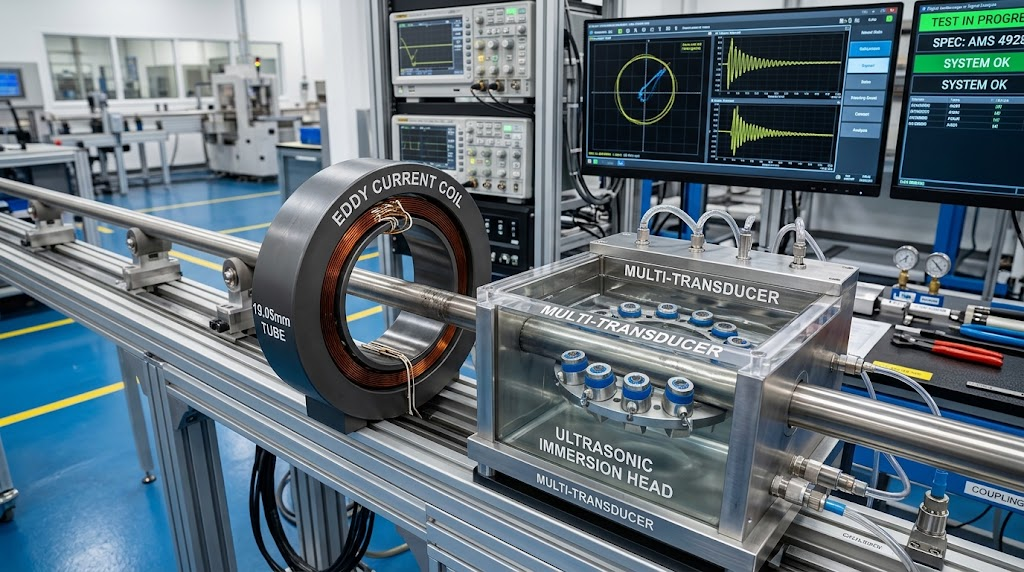
Before precision machining, all raw medical bar stock must undergo non-destructive inspection. The baseline requirement for critical surgical hardware is 100% automated immersion ultrasonic testing (UT) governed by AMS 2631 Class AA standards. Ultrasonic transducers utilize calibration standards featuring flat-bottom holes (FBH) of 0.79 mm (2/64-inch) diameter to scan the volume of every Titanium Bar. Any internal acoustic anomaly that exceeds the echo response of the Class AA reference reflector—or produces an attenuation loss of back-reflection exceeding 50%—results in material rejection. This protocol screens out sub-surface pipe shrinkages, micro-voids, and metallic inclusions before raw stock reaches CNC machining operations.
Swiss-Type CNC Turning & 5-Axis Micro-Milling Dynamics for Implants
Machining complex orthopedic trauma screws, miniature dental abutments, and contoured anatomical bone plates requires rigid machine tool kinematic configurations. Swiss-type CNC lathes and simultaneous 5-axis micro-milling centers are standard platforms for processing these geometries. Swiss lathes, which feed bar stock through a precision carbide guide bushing directly adjacent to the cutting tools, provide maximum dynamic rigidity. This setup eliminates work deflection along extended lengths, enabling the production of slender, high-aspect-ratio implant components.
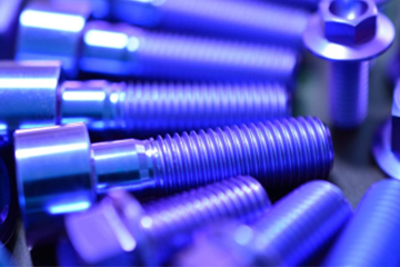
These kinematics provide stability when executing multi-start, variable-pitch thread profiles on cancellous and cortical bone screws. Thread whirling attachments utilize high-speed revolving cutter heads tilted to the exact thread helix angle. The cutter teeth enter and exit the rotating titanium rod stock with minimal contact time, reducing tool pressure, clearing chips efficiently, and preventing burr formation at thread crests. This approach avoids the high tool deflection, excessive cycle times, and localized heat generation typical of single-point threading tools.
Simultaneous 5-axis CNC machining centers running high-speed spindles (up to 30,000 to 42,000 RPM) use continuous tool vectoring to machine complex orthopedic surfaces. Tilting the spindle tool vector relative to anatomical CAD models enables the use of short, rigid endmills with minimal stickout. This maintains consistent chip loads and prevents regenerative tool chatter when milling thin walls and deep contoured profiles. Advanced kinematic configurations allow complex parts to be machined in a single setup, maintaining true geometric position tolerances of ≤ 0.010 mm across multiple intersecting anatomical planes.
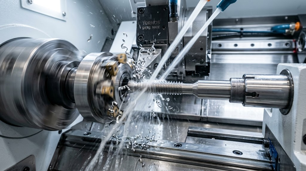
Centerless Ground h6/h5 Bar Stock Integration in Swiss Guide Bushings
The operational efficiency and dimensional accuracy of a Swiss-type sliding-headstock lathe depends on the fit between the raw stock's outer diameter and the inner bore of the carbide guide bushing. Standard commercial drawn or peeled rod stock, which often features loose h9 or h11 tolerances, is unsuitable for high-precision implant manufacturing. Variable rod stock dimensions cause fluid boundary collapse inside the bushing, leading to seizure, excessive guide bushing clearance, dynamic bar whip, micro-chatter, and loss of concentricity during deep cannulation drilling.
| Bar Stock Parameter | ISO Class h6 Specification | ISO Class h5 Specification | Impact on Swiss CNC Turning Performance |
|---|---|---|---|
| Diameter Tolerance (Ø ≤ 6 mm) | +0 / -0.008 mm (+0 / -0.00031 in) | +0 / -0.005 mm (+0 / -0.00020 in) | Eliminates guide bushing binding and minimizes radial play during turning. |
| Diameter Tolerance (Ø 6–10 mm) | +0 / -0.009 mm (+0 / -0.00035 in) | +0 / -0.006 mm (+0 / -0.00024 in) | Maintains hydro-dynamic oil barrier inside the rotating Swiss bushing. |
| Diameter Tolerance (Ø 10–18 mm) | +0 / -0.011 mm (+0 / -0.00043 in) | +0 / -0.008 mm (+0 / -0.00031 in) | Stabilizes deep boring and high-aspect bone screw thread whirling. |
| Circularity / Roundness (Out-of-Round) | ≤ 0.003 mm (0.00012 in) | ≤ 0.0015 mm (0.00006 in) | Prevents ovality transfer to pitch diameter and Morse taper mating cones. |
| Straightness Tolerance | ≤ 0.5 mm / 1000 mm length | ≤ 0.3 mm / 1000 mm length | Eliminates rotational harmonics and bar feed channel vibration at 8000 RPM. |
| Surface Roughness (Ra) of Raw Bar | Ra ≤ 0.4 μm (16 μin) | Ra ≤ 0.2 μm (8 μin) | Prevents abrasive scoring and premature wear of the carbide bushing lining. |
Precision centerless grinding transforms raw, rough-turned or extruded titanium rods into dimensionally stable feedstock. Operating Swiss machines with h6 or h5 centerless ground stock allows the guide bushing clearance to be maintained at an exact 0.003 mm to 0.005 mm diametral gap. This tight clearance stabilizes the bar as the Z-axis feeds forward through the bushing face. It provides steady tool engagement during interrupted cuts, prevents micro-chatter, and eliminates pitch runout when machining bone screws with lengths exceeding 20 times their root diameter.
Rotational bar straightness is equally critical. When spinning 3-meter bars up to 10,000 RPM inside magazine bar loaders, any straightness deviation exceeding 0.5 mm per meter generates destructive centrifugal forces and dynamic imbalances. These vibrations travel through the guide bushing, manifesting as surface chatter marks and tool edge chipping. They can also cause guide wire drill bits to drift off-center during deep cannulation drilling. Specifying precision-ground, stress-relieved titanium rods ensures dynamic spindle stability and reduces dimensional variation throughout continuous production runs.
Thermal Dissipation, Work-Hardening & Eliminating the Machined White Layer
Machining titanium alloys involves challenging thermal dynamics. Dual-phase Ti-6Al-4V ELI exhibits low thermal conductivity (6.7 W/m·K at room temperature, compared to 398 W/m·K for copper and 52 W/m·K for plain carbon steel). Consequently, the plastic deformation energy generated in the shear zone does not dissipate into the chips or surrounding atmosphere. Instead, approximately 80% of the cutting heat concentrates directly in the primary shear zone and adjacent tool nose radius.
This heat concentration, combined with titanium's chemical reactivity at elevated temperatures (> 500°C), accelerates tool wear mechanisms, including cratering, notch wear, and micro-welding at the cutting edge. Furthermore, when titanium is cut with worn tooling (flank wear land VB exceeding 0.12 mm) or excessive surface cutting speeds (vc > 55 m/min under dry conditions), the high temperatures and severe shear strains induce localized microstructural damage. This results in the formation of a brittle, work-hardened subsurface layer termed the "machined white layer."
The white layer consists of an oxygen-enriched, severely plastically deformed nanocrystalline structure that exhibits high hardness (often exceeding 600 HV, compared to the core alloy's 330–350 HV) along with micro-cracking and high residual tensile stresses. Under cyclical mechanical loads in physiological environments, this brittle layer acts as a primary site for fatigue crack initiation. Research indicates that components containing a machined white layer greater than 10 μm thick experience up to a 45% reduction in high-cycle dynamic fatigue life compared to components with stress-free surfaces.
To eliminate white layer formation, maintain surface integrity, and control work-hardening, machine operators must follow strict machining parameters:
Sub-Micron Grain Tungsten Carbide Substrates: Use fine-grain WC-Co substrates (grain size 0.5–0.8 μm) with 6% to 10% cobalt content, providing high edge toughness and wear resistance.
Positive Rake Cutting Geometry: Utilize ground inserts with high positive rake angles (γ = 10° to 15°) and sharp, micro-honed edge radii (rε ≤ 5–10 μm) to promote clean shear cutting rather than material burnishing.
PVD Physical Coatings: Apply thin (1.5–3.0 μm) PVD TiAlN, AlTiN, or AlCrN coatings with low friction coefficients, high oxidation resistance up to 900°C, and smooth surfaces to reduce built-up edge formation. Avoid thick CVD coatings, which can induce micro-cracks that initiate tool chipping.
High-Pressure Coolant (HPC): Deliver high-pressure cutting fluid (70 to 140 bar / 1000 to 2000 PSI) directed through the tool holder directly into the tool-chip interface. This high-velocity fluid penetrates the thermal vapor blanket, flushes heat from the cutting zone, curls chips, and maintains temperatures well below the beta-transus transformation threshold.
5-Axis Simultaneous Milling for Spinal Cages, Femoral Stems & Cranial Plates
Simultaneous 5-axis micro-milling enables the production of anatomically contoured geometries directly from certified raw titanium plate or forged bar stock. Interbody spinal fusion cages, contoured trauma plates, and hip arthroplasty stems require precise spatial positioning across intersecting angular planes. In these applications, true position must be maintained across multiple anatomical surfaces.
| Medical Device Class | Critical Geometric Features | Primary Milling Kinematics & Strategy | Tolerance & Roughness Achieved |
|---|---|---|---|
| Spinal Interbody Fusion Cages | Porous lattice interface, directional pyramidal serrations, internal grafting windows. | Simultaneous 5-axis high-speed milling; dynamic trochoidal strategies to clear small pockets without tool stalling. | Profile: ±0.012 mm; Serration pitch: ±0.008 mm; Ra: 0.8–1.6 μm (promotes bone anchoring). |
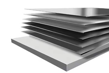
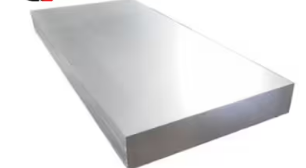
| Anatomical Trauma Bone Plates | Contoured skeletal profiles, complex threaded screw holes, dynamic compression slots. | 5-axis simultaneous contouring from stress-relieved Titanium Plate; helical interpolation for variable-angle locking holes. | Contour: ±0.020 mm; Hole true position: ≤ 0.015 mm; Ra: ≤ 0.4 μm (tissue contact side). |
| Femoral Arthroplasty Hip Stems | Double-tapered cross-sections, longitudinal stabilization ribs, high-precision modular taper necks. | Multi-axis simultaneous flank and point milling; single-setup turning-milling to minimize runout on the modular Morse taper. | Morse taper angle: ±0.0025°; Taper circularity: ≤ 0.003 mm; Ra: ≤ 0.2 μm (mating taper). |
| Cranio-Maxillofacial (CMF) Plates | Thin-web mesh patterns (thickness 0.45–0.60 mm), countersink screw landings. | High-speed 5-axis micro-milling using balanced vacuum/micro-vise fixtures to prevent thin-wall deflection. | Wall thickness: ±0.008 mm; Complete burr-free edge profile without manual reworking. |
When milling thin-gauge cranial plates or structural trauma profiles from ASTM F136 or F67 plate stock, elastic deflection requires careful compensation. Titanium's modest modulus of elasticity (110 GPa—roughly half that of austenitic stainless steel) leads to springback when tools exert lateral cutting forces on slender walls. Minimizing deflection requires optimized CAD/CAM toolpaths, such as balanced climb-milling, adaptive trochoidal slicing, and constant step-down engagement depths. This controls tool pressure, prevents work distortion, and ensures consistent wall thicknesses across the entire component geometry.
Surface Integrity, Biocompatibility Cleaning & Post-Machining Validation
Fabricating a titanium implant on a CNC machine is only the first step in medical device production. A precisely machined part is not yet suitable for surgical implantation. Post-machining surface chemistry and cleanliness are equally critical, as microscopic residues can affect biological response in vivo. Cutting fluids, microscopic tool wear particles, airborne particulates, and residual hydrocarbon films can induce sterile inflammation, soft-tissue necrosis, or foreign-body reactions if not completely removed prior to packaging and sterilization.
Transforming raw, machined titanium components into compliant medical devices requires a validated sequence of post-processing operations. These steps include chemical cleaning, surface passivation, and electrochemical anodization. These processes must adhere strictly to international standards, including ISO 10993 (Biological Evaluation of Medical Devices), ASTM F86 (Standard Practice for Surface Preparation and Marking of Metallic Surgical Implants), and AMS 2488 (Anodic Treatments for Titanium and Titanium Alloys). Together, these surface treatments ensure the implant is free of toxic residues and exhibits a stable, biocompatible oxide layer.

The choice of cutting fluid for machining implant-grade titanium is subject to strict chemical and biological constraints. Standard industrial cutting fluids often contain chlorinated paraffin, sulfurized boundary additives, silicone antifoams, and biocides like formaldehyde-releasing agents. These chemical compounds are problematic for surgical implants. Chlorinated compounds can induce localized stress corrosion cracking in titanium alloys at elevated autoclave sterilization temperatures (> 121°C). Residual trace sulfur or synthetic biocides can cause biological rejection, leading to failures during ISO 10993-5 in vitro cytotoxicity testing.
Medical manufacturing facilities utilize certified water-soluble synthetic emulsions or high-purity medical-grade vegetable neat cutting oils that are formulated free of chlorine, sulfur, silicones, and heavy metals. Once machining is complete, components undergo a validated multi-stage aqueous ultrasonic cleaning process conducted within a controlled cleanroom environment (ISO Class 7 or Class 8 per ISO 14644):
Stage 1: Multi-Frequency Ultrasonic Degreasing: Immersion in a heated (55°C–65°C) mild alkaline saponifying bath (pH 9.5–11.0) using sweep-frequency ultrasonic agitation (40 kHz / 80 kHz / 120 kHz). This combination emulsifies neat oils, disperses fine metal particulates, and prevents the redeposition of microscopic debris within small blind tapped holes and cannulated lumens.
Stage 2: Cavitation Vacuum Degassing: Ultrasonic cleaning cycles run under vacuum to eliminate air pockets within fine internal threads, cross-holes, and porous features, ensuring complete fluid contact across all surfaces.
Stage 3: Cascading Deionized Water Rinsing: Successive immersion rinses using high-purity deionized (DI) water with electrical resistivity maintained at ≥ 18 MΩ·cm at 25°C. This cascading counter-current rinse removes residual alkaline cleaning agents and dissolved particulates.
Stage 4: Residual Endotoxin & Cleanliness Validation: Finished parts undergo Limulus Amebocyte Lysate (LAL) testing per ANSI/AAMI ST72 to verify that bacterial endotoxin concentrations remain below the strict limit of < 20 endotoxin units (EU) per device (or < 2.15 EU/device for products contacting cerebrospinal fluid). Total organic carbon (TOC) analysis and gravimetric hydrocarbon testing confirm cleanliness.
Stage 5: HEPA-Filtered Thermal Drying: Parts are dried in vacuum ovens equipped with Class 100 HEPA air filtration to prevent airborne particulate contamination prior to passivation.
ASTM F86 Nitric/Citric Passivation & Free-Iron Eradication
During Swiss turning and milling operations, titanium stock comes into mechanical contact with tungsten carbide tooling, tool steel guide bushings, hardened steel collets, and stainless steel handling fixtures. This mechanical interaction can cause microscopic iron particles to transfer onto the titanium surface. In oxygenated physiological saline, this embedded free iron disrupts the native passive film and forms micro-galvanic cells. This accelerates localized pitting corrosion, degrades biocompatibility, and can cause systemic release of heavy-metal ions.
To eliminate this contamination, components undergo chemical passivation per ASTM F86 guidelines. The passivation process selectively dissolves surface free iron, traces of cobalt binder leached from carbide tooling, and other exogenous metallic contamination. At the same time, the oxidizing chemistry thickens and stabilizes the material's protective titanium dioxide (TiO2) passive layer.
| Passivation Chemistry & Method | Standard Concentration & Bath Parameters | Processing Window | Operational Mechanisms & Limitations |
|---|---|---|---|
| ASTM F86 Method A (Nitric Acid) | 20% to 40% volume HNO3 in DI water; Optional 2% wt Na2Cr2O7 (sodium dichromate) | Temperature: 45°C to 60°C; Immersion: 30 to 45 minutes | Aggressive oxidant; dissolves free iron and thickens TiO2 film to 4–6 nm. Generates NOx emissions requiring exhaust scrubbing. |
| ASTM F86 Method B (Citric Acid) | 4% to 10% weight C6H8O7 (citric formulation with chelating agents) | Temperature: 50°C to 65°C; Immersion: 20 to 30 minutes | Selectively chelates Fe2+/Fe3+ ions; environmentally friendly; zero heavy metal waste; reduces risk of hydrogen pickup. |
Careful monitoring of the acid bath is critical to prevent hydrogen pickup. In uninhibited, non-oxidizing, or reducing acid environments (such as contaminated or improperly mixed baths), titanium can absorb nascent monoatomic hydrogen into its crystal lattice. Hydrogen diffusion into interstitial lattice sites can precipitate brittle titanium hydrides (TiH2) at grain boundaries. This leads to slow-strain-rate hydrogen embrittlement and catastrophic failure under dynamic loads. Maintaining bath oxidation potential and controlling maximum immersion times prevents hydrogen pickup, keeping internal hydrogen concentrations below the ASTM F136 threshold of 120 ppm (0.012 wt%). Surface purity is then verified using potassium ferricyanide testing or X-ray Photoelectron Spectroscopy (XPS) depth profiling per ASTM F86.
AMS 2488 Type II vs. Type III Color Anodizing & Micro-Deburring
Following cleaning and passivation, surgical implants often undergo specialized surface engineering to optimize mechanical performance, improve tribological properties, or provide clear visual identification in clinical settings. The two primary electrochemical treatments for implantable titanium are AMS 2488 Type II hard anodizing and Type III optical color anodizing.
AMS 2488 Type II anodizing is an alkaline electrolytic conversion process that produces a dense, dark-gray surface conversion layer measuring 1.5 to 2.5 μm in thickness. Operating in a high-pH bath (pH > 12, typically utilizing concentrated NaOH or KOH solutions with applied current densities of 10 to 30 A/ft2), this conversion treatment transforms the surface into a wear-resistant, anti-galling layer. Type II anodizing provides distinct functional benefits:
Anti-Galling and Fretting Protection: It prevents cold-welding and adhesive galling between threaded titanium components, such as locking bone screws engaging threaded trauma plate holes or pedicle screw locking set screws.
Enhanced Dynamic Fatigue Performance: By smoothing localized micro-asperities and reducing the friction coefficient under micro-motion, Type II anodizing can increase fretting fatigue life by 20% to 35% compared to untreated titanium surfaces.
In contrast, Type III color anodizing is an acid-bath electrolytic process (typically utilizing mild phosphoric, sulfuric, or organic acid electrolytes) that produces a thin, transparent, non-porous titanium dioxide film ranging from 30 to 200 nanometers thick. Type III anodizing does not use artificial dyes or pigments. Instead, color is generated through optical light interference: light reflecting off the outer oxide surface interferes with light reflecting off the underlying titanium substrate. The resulting color corresponds directly to the precise thickness of the oxide layer, which is controlled by varying the applied bath voltage (e.g., 14V produces bronze, 28V produces purple, 45V produces blue, and 75V produces green).
Type III anodizing enables quick optical identification of screw diameters, drill sizes, and left/right anatomical plates in the operating room, reducing surgical errors during implantation. Because the oxide layer is thin (≤ 0.2 μm), it does not alter tight CNC machining tolerances. However, it provides lower wear and galling resistance than AMS 2488 Type II treatments.
Before anodizing, all components must undergo micro-deburring. Residual micro-burrs along bone screw threads, cannulation holes, or suture eyelets can detach in vivo, causing foreign-body tissue irritation. Medical-grade deburring relies on controlled isotropic superfinishing (vibratory tumbling with non-abrasive ceramic media and acidic surfactants), centrifugal disc finishing, or electrochemical polishing. These methods yield smooth edge breaks (radii: 0.05 mm to 0.15 mm) while achieving target surface finishes from Ra 0.2 μm (mating taper surfaces) to Ra 0.8 μm (bone attachment areas) without manual handling.
Operational Boundaries, Failure Modes & DFM Guidelines for Implant Engineers
While titanium is often considered the standard material for surgical implants, it has definite operational limitations. Incomplete understanding of its mechanical, electrochemical, and tribological characteristics can lead to clinical device failures. Medical device design engineers must consider these limitations during product development and establish appropriate Design for Manufacturability (DFM) rules. Designing to prevent these known failure modes reduces production scrap, simplifies machining setups, and ensures long-term in vivo device stability.
Tribological Taboos: Fretting Wear, Adhesive Galling & Galvanic Coupling
The primary mechanical limitation of both commercially pure titanium and dual-phase Ti-6Al-4V ELI is their poor tribological behavior. Uncoated titanium exhibits high coefficients of friction (μ = 0.35–0.50 against itself or other metals) and low shear strength along its hexagonal basal planes. When subjected to sliding or micro-motion under load, the thin native TiO2 passive layer rapidly shears away. The exposed, chemically reactive titanium surfaces cold-weld upon contact, leading to adhesive galling, material transfer, and surface degradation.
This wear mechanism is problematic in modular orthopedic junctions, such as the Morse taper trunnion connection between a Ti-6Al-4V femoral hip stem and a cobalt-chromium (CoCrMo) or ceramic modular head. Micro-motion in the presence of synovial fluid causes fretting wear and mechanically assisted crevice corrosion—a clinical condition known as trunnionosis. This process releases sub-micron titanium debris and soluble metal ions into the surrounding periprosthetic joint space, which can trigger adverse local tissue reactions (ALTR), pseudo-tumors, and osteolysis, ultimately requiring revision surgery.
To mitigate these tribological risks, implant engineers should follow clear operational boundaries:
Avoid Direct Metal-on-Metal Articulation: Never specify bare, uncoated titanium alloys for articulating joint surfaces (such as femoral heads against acetabular cups, or unicondylar knee wear tracks). For articulating wear couples, use cross-linked polyethylene (UHMWPE) articulating against PVD titanium nitride (TiN)-coated substrates, ceramic materials (Alumina/Zirconia matrices), or cobalt-chromium alloys.
Prevent Modular Taper Galling: Apply AMS 2488 Type II anodizing to the male taper, maintain precise contact angular tolerances (taper angle mismatch controlled within ±0.002° / ±7 arcseconds), and specify clean assembly protocols with calibrated surgical torque-wrenches.
Avoid Problematic Galvanic Couples: Titanium's high nobility makes it resistant to corrosion when coupled to passive austenitic stainless steels (such as 316LVM) or CoCrMo in physiological fluid. However, pairing titanium with active, non-passivated, or dissimilar materials can create localized galvanic cells. Avoid mixing dissimilar materials within modular constructs unless validated by ASTM F2129 in vitro electrochemical cyclic potentiodynamic polarization testing.
DFM Tolerances for Cannulated Bone Screws, Thin-Wall Cages & Bone Plates
Designing components that are cost-effective to machine while maintaining structural and functional integrity requires adhering to specific Design for Manufacturability (DFM) rules. The following matrix details engineering limits and machining guidelines for common titanium implant geometries:
| Design Feature | Recommended DFM Minimum | Critical Machining Bottleneck | Manufacturing Failure Prevention Strategy |
|---|---|---|---|
| Cannulation Bore (Bone Screws) | Ø ≥ 1.0 mm; Length-to-Diameter (L/D) ≤ 15:1 | Gun-drill drift, chip packing, tool breakage inside the part. | Use through-tool high-pressure oil (100 bar); specify concentricity tolerances of ≤ 0.020 mm; maintain guide bushing clearance at h6/h5. |
| Thin Walls (Spinal Cages & Plates) | Wall thickness ≥ 0.45 mm (0.018 in) | Elastic springback deflection during endmilling; wall vibration. | Implement adaptive climb milling with small radial step-overs (ae ≤ 5% tool diameter); avoid localized clamping deformation. |
| Internal Pocket Radii | Radius R ≥ 0.25 mm (0.010 in); Prefer R ≥ 1.0 × depth/4 | Micro-endmill deflection, tool breakage, cyclic stress concentration. | Avoid sharp internal corners (stress concentration Kt > 3.0); use 5-axis tool tilting to permit larger diameter, more rigid endmills. |
| Bone Screw Thread Roots | Continuous radius root: R ≥ 0.10 mm to 0.15 mm | Notch-sensitivity fatigue failure at the first engaged screw thread. | Specify custom buttress or reverse-buttress thread profiles with generous root radii produced via dedicated multi-tooth whirling cutters. |
| Drive Hexalobe / Torx Sockets | Standard ISO 10664 features; internal depth ≤ 1.5× width | Rotary broaching stalls; incomplete bottom-of-pocket chip evacuation. | Machine an undercut relief groove at the bottom of the socket, or use high-speed 5-axis micro-milling to form the lobes rather than push broaching. |
ISO 13485 Quality Assurance, Metrology & Full Lot Traceability
Operating a high-reliability machining facility for implantable titanium components requires an integrated Quality Management System (QMS). In the medical sector, ISO 13485:2016 compliance is the baseline requirement. Unlike general industrial manufacturing, where quality control relies heavily on end-of-line sampling, medical implant manufacturing requires comprehensive risk management, validated machining processes, and continuous lot traceability linking raw melt ingots to final serialized packaging.
Every production batch must maintain an unbroken chain of documentation captured in the Device History Record (DHR). Traceability begins with the raw material manufacturer's certified EN 10204 3.1 Mill Test Certificate (MTC). The MTC must document the primary sponge origin, Triple-VAR melt heat number, complete interstitial and substitutional chemical composition, beta-transus transformation temperature, ASTM E8 tensile and yield data, ASTM E112 microstructural grain size verification, and AMS 2631 Class AA ultrasonic flaw detection sign-offs.
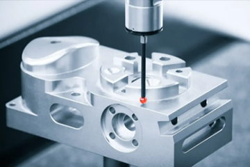
Prior to production release, every new implant geometry undergoes First Article Inspection (FAI) per AS9102 or ISO 13485 protocols. Metrology verification requires cleanroom-grade inspection tools. Highly contoured, flexible, or miniature features—such as bone screw threads and thin cranial plates—are inspected using multi-sensor non-contact optical CMM platforms, dual-axis laser telecentric gauging, and confocal white-light interferometry. These non-contact methods measure pitch diameters, lead errors, and surface finishes (Ra, Rz, Rmax) without physically deflecting the part.
For high-volume production, dimensional stability is maintained through continuous Statistical Process Control (SPC). Critical-to-Quality (CTQ) dimensions—including the pitch diameter of cortical bone screws, the Morse taper angle of hip trunnions, and the guide-hole true positions of trauma plates—are monitored for process capability. Machining operations must achieve and maintain process capability indices of Cpk ≥ 1.33 for standard dimensions and Cpk ≥ 1.67 for designated critical features. This statistical confidence demonstrates that tool wear, thermal expansion, and bar-feeder vibrations are tightly controlled throughout continuous unattended production runs.
Technical Verification & Procurement FAQ for Medical Titanium Machining
1. How is the absence of alpha-case and work-hardened white layers verified on machined implants?
Verifying the absence of alpha-case and white layers requires metallographic sectioning and destructive micro-indentation hardness testing on representative witness samples from each machining lot. Samples are mounted, ground, and polished to a mirror finish, then etched with Kroll's reagent (2% HF, 4% HNO3, 94% H2O) to reveal the microstructure. Under optical and scanning electron microscopy (SEM) at 500x to 1000x magnification, an altered white layer appears as a continuous, unetched, light-colored surface boundary. This visual inspection is complemented by Knoop or Vickers microhardness profiles (ASTM E384) using a light 15-gram or 25-gram load, taking measurements in 2 μm increments starting 2 μm below the surface. Hardness readings that exceed the core base metal hardness by more than 40 HV point to localized oxygen enrichment or severe work hardening, requiring adjustments to cutting speeds, tool wear limits (VB ≤ 0.10 mm), and high-pressure coolant delivery.
2. What straightness and dimensional tolerances are mandatory on ASTM F136 bar stock for Swiss turning?
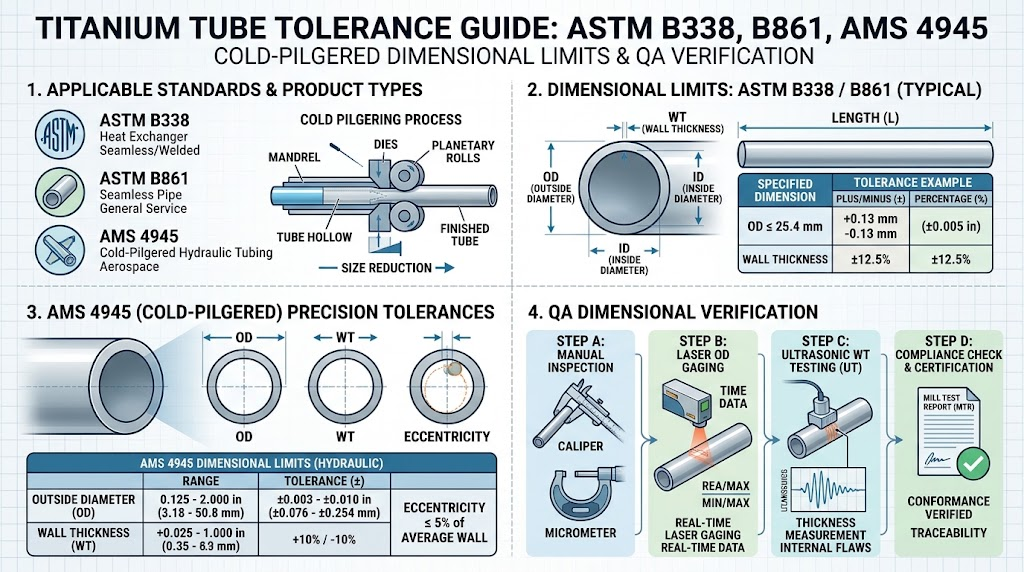
To run reliably in high-speed Swiss-type guide bushings without binding, bar whip, or tool chatter, ASTM F136 Grade 23 titanium bar stock must be centerless ground to ISO h6 or h5 dimensional tolerances. For bar diameters between 3.0 mm and 10.0 mm, an h6 tolerance specifies a diameter window of +0 / -0.009 mm (+0 / -0.00035 in). Out-of-roundness (circularity) must not exceed 0.002 mm, and raw surface roughness must maintain Ra ≤ 0.4 μm to prevent abrasive wear against the internal carbide guide bushing faces. Straightness is equally critical: bar stock must meet a straightness specification of ≤ 0.5 mm per 1000 mm of length (ideally ≤ 0.3 mm/m). This straightness eliminates centrifugal vibrations and harmonic chatter when spinning up to 10,000 RPM, maintaining dimensional accuracy and bore concentricity during deep cannulation drilling.
3. How is hydrogen pickup prevented during the acid passivation of thin-walled implants?
Preventing hydrogen pickup during ASTM F86 chemical passivation requires maintaining the oxidation potential of the acid bath and using validated immersion parameters. Hydrogen absorption occurs when titanium comes into contact with non-oxidizing or reducing acids, which generate monoatomic hydrogen (H⁺) that diffuses into the crystal lattice. When using nitric acid (ASTM F86 Method A), the bath must maintain a concentrated oxidizer level (20% to 40% volume HNO3), which passivates the metal surface and promotes the formation of a protective TiO2 barrier that blocks hydrogen entry. If using citric acid formulations (Method B), specialized chelating agents and bath oxidizers must be maintained within controlled temperature (50°C–65°C) and time (20–30 minutes) limits. Bulk chemical lots are qualified by measuring total hydrogen content before and after passivation via inert gas fusion thermal conductivity testing per ASTM E1447, verifying that hydrogen remains below the 120 ppm threshold.
4. What documentation package accompanies production shipments for FDA 21 CFR Part 820 compliance?
Every shipment of medical implant components must include a complete, traceable Device History Record (DHR) package compliant with FDA 21 CFR Part 820.184 and ISO 13485 regulations. The documentation package contains: 1) The original EN 10204 3.1 Mill Test Certificate tracing the batch to the raw material ingot, documenting Triple-VAR melt heats, mechanical tensile properties, interstitial gas analysis, and AMS 2631 Class AA ultrasonic test verification; 2) Certificate of Conformance (CoC) confirming that all CNC machining, deburring, and surface finishing steps adhere to the customer's drawing specifications and revision level; 3) Dimensional First Article Inspection (FAI) report per AS9102, along with continuous Statistical Process Control (SPC) Cpk data logs for all designated CTQ dimensions; 4) Passivation and anodizing validation certificates verifying compliance with ASTM F86 and AMS 2488; 5) Cleaning validation and cleanliness reports, including residual hydrocarbon test results and LAL endotoxin testing (ANSI/AAMI ST72) confirming levels below 20 EU/device.
Related Technical Specifications & Material Grade Hub & Engineering Consultation
Achieving predictable performance in medical implant manufacturing requires matching part design with the appropriate material grade and machining process. The engineering matrix below details complementary wrought titanium grades available for precision CNC Swiss turning, multi-axis milling, and custom implant manufacturing:
| Material Grade & Specification | Metallurgical Structure | Primary Mechanical Thresholds | Primary Medical Device Applications |
|---|---|---|---|
| ASTM F136 Grade 23 (Ti-6Al-4V ELI) | Equiaxed Alpha-Beta | Rm ≥ 860 MPa; Rp0.2 ≥ 795 MPa; Elongation ≥ 10%; O ≤ 0.13% | Spinal pedicle screws, rods, orthopaedic plates, marrow nails, hip stems. |
| ASTM F67 Grade 4 (Cold-Worked CP) | High-Strength Pure Alpha | Rm ≥ 680–750 MPa; Rp0.2 ≥ 520 MPa; Elongation ≥ 12%; V/Al Free | Endosseous dental implants, abutments, transgingival collars, CMF screws. |
| ASTM F67 Grade 2 (Unalloyed CP) | Ductile Commercially Pure Alpha | Rm ≥ 345 MPa; Rp0.2 ≥ 275 MPa; Elongation ≥ 20%; High Malleability | Malleable maxillo-facial plates, cranial defect mesh, pacemaker enclosures. |
| ASTM F1295 (Ti-6Al-7Nb) | Equiaxed Alpha-Beta (V-Free) | Rm ≥ 900 MPa; Rp0.2 ≥ 800 MPa; High Bio-Inertness & Notch Fatigue | High-load femoral hip stems, knee revision components, spinal hardware. |
| ASTM B348 Grade 5 (Ti-6Al-4V Industrial) | Standard Wrought Alpha-Beta | Rm ≥ 895 MPa; Rp0.2 ≥ 828 MPa; O ≤ 0.20%; Fe ≤ 0.40% | External surgical instrumentation, drill guides, retractors, sterilization trays. |
Technical Consultation & Mill Test Certificate (MTC) Requests
To assist with your device development, tooling setup, or ISO 13485 production transfer, the engineering team at China Titanium Factory offers our 3-Step Manufacturing Review Protocol:
Submit your 3D CAD files (STEP, IGES) and 2D drawing prints with GD&T specifications, identifying Critical-to-Quality dimensions, target ASTM/ISO material grades, and surface finish requirements.
Within 12 hours, receive a Design for Manufacturability (DFM) review analyzing wall thicknesses, thread dynamics, and tool access, along with a certified sample EN 10204 3.1 MTC and an AMS 2631 Class AA ultrasonic inspection dossier.
Schedule a direct video technical consultation with our Metallurgical and Machining Applications Engineers to review tool paths, finalize quality acceptance criteria, and plan pilot runs.