


















Titanium Tube Tolerance Guide: ASTM B338, B861, AMS 4945 Cold-Pilgered Dimensional Limits & QA Verification
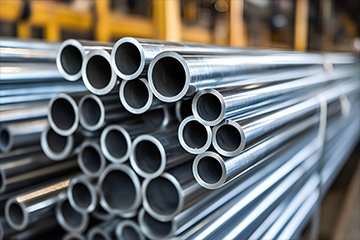
Precision tube manufacturing in reactive refractory metals demands exact dimensional discipline. Achieving dimensional conformance across titanium product forms requires an understanding of cold work recovery, deformation mechanics, and standard specification boundaries. The engineering trade-offs governing cold-pilgered and welded tubular products are defined primarily by standard specifications: ASTM B338 Seamless & Welded Titanium Heat Exchanger Tubes, ASTM B861 Seamless Titanium Pipe Schedule & Dimensional Standards, and aerospace standards including AMS 4945. These standards control outer diameter (OD), inner diameter (ID), wall thickness (WT), and ovality across demanding operational environments.
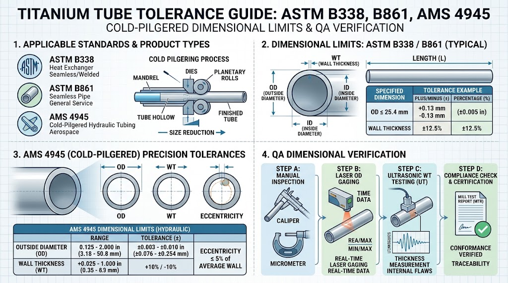
Standard commercial tubing lines rely on conventional multi-pass draw benches, which often produce wide dimensional distributions. By contrast, critical applications—such as TEMA Class R heat exchangers, downhole sour gas completions, and aerospace hydraulic transmission lines—require tight dimensional control. For these environments, 3-roll high-precision Long-Die (LD) cold-pilgering provides distinct advantages over 2-roll configurations. The 3-roll process applies compressive, triaxial radial stresses during reduction, compressing standard ASTM B338 tolerances by 50% to 70%. It simultaneously controls outer diameter variations within ±0.03 mm to ±0.05 mm and restricts wall thickness variation to ±5%, compared to the nominal ±10% Average Wall or +20% / -0% Minimum Wall limits allowed by standard industrial codes.
Achieving tight dimensional boundaries requires full metallurgical traceability and in-process metrology. This process begins with Vacuum Arc Remelting (VAR) or Electron Beam Cold Hearth Melting (EBCHM) titanium sponge ingots and continues through multi-axis laser micrometer profiling, dual-frequency eddy current flaw detection, and 8-channel ultrasonic immersion testing. Understanding these dimensional parameters and non-destructive testing (NDT) limits is essential for QA managers, stress analysts, and procurement directors to prevent field failures, tube-to-tubesheet joint leaks, and unexpected procurement costs.
1. Outer Diameter (OD) & Inner Diameter (ID) Permissible Variations
2. ASTM B338 vs. ASTM B861 Standard OD Tolerances by Size Range
3. Precision Cold-Pilgered & Mandrel-Drawn Tight OD/ID Capabilities
4. Impact of OD Tolerance & Roller Expansion on Heat Exchanger Tubesheet Fit-Up
5. Wall Thickness (WT) Tolerances, Procurement Cost Mechanics & Eccentricity Control
6. Average Wall (±10%) vs. Minimum Wall (+20% / -0%) Engineering & Cost Matrix
8. Wall Eccentricity Formulas & High-Pressure Aerospace Hydraulic Burst Ratings
9. Geometric Tolerances: Ovality (Out-of-Roundness), Straightness & Forming Limits
10. Thin-Wall vs. Heavy-Wall Ovality Allowances & Elastic Springback
11. Straightness Measurement Benchmarks (mm per Meter) & Orbital Welding Alignment
12. Destructive Mechanical Verification: Flattening, Flaring & Reverse Flattening Limits
13. Quality Assurance, NDT Metrology & Operational Failure Prevention
14. Continuous Multi-Channel Ultrasonic (UT), Eddy Current & Laser Micrometer Profiling
15. Alpha-Case Descaling, Acid Pickling Allowances & Hydrogen Pickup Taboos
16. Procurement Checklist: Specifying Custom Tolerances on Purchase Orders & EN 10204 3.1 MTCs
17. Technical FAQ: Resolving Titanium Tube Tolerance & Fit-Up Engineering Challenges
Outer Diameter (OD) & Inner Diameter (ID) Permissible Variations
Titanium tube diametral tolerances are determined by the interaction between the alloy's crystalline slip mechanisms, its low shear modulus (approximately 40 to 45 GPa), and the mechanical tooling used during cold finishing. In ASTM B338 Table 5, allowable outer diameter variations are specified based on step-function diameter ranges. Because cold drawing and pilgering induce non-uniform radial displacement, unconstrained tube recovery generates diametral variance. Unless a secondary sizing operation is performed over a calibrated mandrel, the outer diameter tolerance absorbs the accumulated geometric deviations from incoming hollows, tool wear, and machine vibration.
Procurement engineers must recognize that titanium tube specifications do not regulate outer diameter, inner diameter, and wall thickness independently. Under ASTM B338, ASTM B861, and ASME Section VIII Division 1, a tube order may specify OD and WT, or ID and WT, but never all three simultaneously. When OD and WT are specified, the ID becomes a derived dimension, absorbing the combined variations of both the outer diameter and the wall thickness. When evaluating high-precision applications—such as sleeve connections, swaged hydraulic fittings, or deep-well sensor housings—specifying the ID tolerance requires explicit written agreement with the mill. In these cases, the mill must implement calibrated carbide plug drawing passes or 3-roll sizing passes to prevent ID bore variation.
The primary driver of diameter variation during production is the difference between standard fixed-plug drawing and modern rocker-type cold-pilgering. Draw bench operations pull the tube through a conical die over an internal floating or fixed plug. In this setup, frictional heating and cyclic tensile stresses can produce localized necking, leading to slight diametral variations along the length of the tube. By contrast, cold-pilgering reduces the cross-sectional area through cyclic, compressive rolling against a profiled, tapered mandrel. This approach reduces outer diameter runout and prevents the surface scoring typical of draw benches, providing a tighter dimensional envelope across production heats.
ASTM B338 vs. ASTM B861 Standard OD Tolerances by Size Range
A common source of confusion in industrial procurement is the operational difference between tubing specified under ASTM B338 and nominal piping specified under ASTM B861. ASTM B338 covers seamless and welded tubing designed specifically for heat transfer equipment, surface condensers, and evaporators. These applications require precise outer diameter tolerances to ensure proper fit-up with tubesheet holes and internal baffles. By contrast, ASTM B861 governs nominal seamless pipe intended for fluid transport. In ASTM B861, dimensions follow Nominal Pipe Size (NPS) schedules, where tolerances are wider to facilitate field butt-welding and structural spool fabrication.
The table below details standard permissible outer diameter variations across both specifications, along with standard cut-length allowances. These metrics apply directly to commonly specified grades, including Titanium Grade 2 (UNS R50400) Commercially Pure Tubing Specifications and alloyed grades such as Grade 9 and Grade 12.
| Outside Diameter Range (Metric / Imperial) | ASTM B338 OD Permissible Variation | ASTM B861 OD Permissible Variation | Standard Cut-Length Tolerance (≤ 7.6 m / 24 ft) |
|---|---|---|---|
| Under 25.4 mm (Under 1.000 in.) | ±0.102 mm (±0.0040 in.) | +0.40 mm / -0.80 mm (+0.015 in. / -0.031 in.) | +3.18 mm / -0 mm (+0.125 in. / -0 in.) |
| 25.4 mm to 38.1 mm (1.000 to 1.500 in.) | ±0.127 mm (±0.0050 in.) | +0.40 mm / -0.80 mm (+0.015 in. / -0.031 in.) | +3.18 mm / -0 mm (+0.125 in. / -0 in.) |
| 38.1 mm to 50.8 mm (1.500 to 2.000 in.) | ±0.152 mm (±0.0060 in.) | +0.40 mm / -0.80 mm (+0.015 in. / -0.031 in.) | +4.76 mm / -0 mm (+0.187 in. / -0 in.) |
| 50.8 mm to 63.5 mm (2.000 to 2.500 in.) | ±0.178 mm (±0.0070 in.) | +0.79 mm / -0.79 mm (+0.031 in. / -0.031 in.) | +4.76 mm / -0 mm (+0.187 in. / -0 in.) |
| 63.5 mm to 88.9 mm (2.500 to 3.500 in.) | ±0.254 mm (±0.0100 in.) | +0.79 mm / -0.79 mm (+0.031 in. / -0.031 in.) | +6.35 mm / -0 mm (+0.250 in. / -0 in.) |
Under ASTM B338 Section 11, straight cut lengths up to 7.6 meters (24 feet) permit a positive tolerance of +3.18 mm (+0.125 in.) with an absolute negative tolerance of -0 mm. For lengths exceeding 7.6 meters, the positive cut-length allowance increases by 1.59 mm (0.0625 in.) for each additional 3.0 meters (10 feet), up to a maximum positive deviation of +12.7 mm (+0.500 in.). These cut-length allowances must be accounted for during process design. When automated orbital welding heads or modular heat exchanger bundles require strict axial clearances, specifying tighter cut-length tolerances—such as +1.0 mm / -0 mm via secondary CNC saw cutting and end-facing—prevents post-delivery trimming on the shop floor.
Precision Cold-Pilgered & Mandrel-Drawn Tight OD/ID Capabilities (±0.03 mm to ±0.08 mm)
While standard commercial tolerances satisfy the general requirements of ASME Section VIII pressure vessels, high-performance applications—such as aerospace hydraulic distribution lines, medical cannulas, downhole umbilical cores, and precision instrumentation—require tighter dimensional control. In aerospace applications governed by AMS 4943, AMS 4944, and Titanium Grade 9 (Ti-3Al-2.5V) High-Pressure Aerospace Hydraulic Tubing under AMS 4945, standard ASTM B338 tolerances can lead to unacceptable assembly clearance variations in flareless sleeve (MS33514 / AS4395) and swaged ring mechanical joints.
To achieve tolerances within ±0.03 mm to ±0.05 mm, the manufacturing process transitions from conventional draw benches to advanced 3-roll Long-Die (LD) cold-pilger mills. In a 3-roll cold-pilgering setup, three complementary roll dies, driven by conjugate cam mechanisms, converge at 120° intervals around the tube hollow. This configuration reduces the cross-sectional area over a precision-ground, tapered carbide mandrel. The 3-roll configuration applies continuous compressive hydrostatic stress, which minimizes the circumferential tensile stress peaks typical of 2-roll pilgering. As a result, it eliminates the formation of longitudinal side-ribs (flashing) and suppresses wall variation.
| Application Category | Nominal Size Envelope (OD × WT) | Achievable OD Tolerance | Achievable ID Tolerance | Governing Specification |
|---|---|---|---|---|
| Aerospace Hydraulic Lines | 6.35 mm to 25.4 mm × 0.5 mm to 1.65 mm | ±0.038 mm (±0.0015 in.) | ±0.050 mm (±0.0020 in.) | AMS 4945 / BMS 7-234 |
| Medical Endoscopic Shafts | 1.50 mm to 6.00 mm × 0.15 mm to 0.40 mm | ±0.025 mm (±0.0010 in.) | ±0.025 mm (±0.0010 in.) | ASTM F67 / ISO 5832-2 |
| Nuclear & High-Purity Chromatography | 3.18 mm to 12.7 mm × 0.50 mm to 1.24 mm | ±0.030 mm (±0.0012 in.) | ±0.040 mm (±0.0016 in.) | ASTM B338 Special Order |
| Precision Subsea Control Tubing | 9.52 mm to 19.05 mm × 1.00 mm to 2.11 mm | ±0.050 mm (±0.0020 in.) | ±0.060 mm (±0.0024 in.) | API Spec 17E / ISO 13628-5 |
For small-diameter capillary and instrumentation tubing (OD < 3.0 mm), cold pilgering reaches its mechanical tooling limit. At this scale, tight tolerances are maintained using multi-pass drawing with fixed tungsten carbide or monocrystalline diamond mandrels. This approach uses reduced area reductions per pass (12% to 18% per draw pass) interspersed with intermediate vacuum recrystallization anneals at 680°C to 720°C in an ultimate vacuum of ≤ 10⁻⁴ Pa. These parameters prevent galling and localized micro-shearing, maintaining surface roughness tolerances of Ra ≤ 0.4 μm on both the outer diameter and inner bore.
Impact of OD Tolerance & Roller Expansion on Heat Exchanger Tubesheet Fit-Up
In shell-and-tube heat exchangers built to TEMA (Tubular Exchanger Manufacturers Association) Class R, C, or B standards, the outer diameter tolerance of the titanium tube directly affects the mechanical integrity of the tube-to-tubesheet expanded joint. Standard tubesheet hole drilling follows TEMA Table RCB-7.41, which establishes nominal drill hole diameters. For example, for a 25.40 mm (1.000 in.) nominal OD tube, the standard 'Special Close Fit' tubesheet hole diameter ranges from 25.60 mm to 25.75 mm, establishing an initial diametral clearance between 0.20 mm and 0.45 mm.
If a mill supplies titanium tubing at the high limit of standard ASTM B338 tolerances (+0.127 mm), the initial diametral clearance decreases, complicating tube insertion across multi-pass baffle assemblies. Conversely, if the supplied tubing sits at the bottom limit (-0.127 mm) and is installed in a tubesheet hole drilled near its maximum permissible machining tolerance, the initial diametral clearance can exceed 0.55 mm. Excessive initial clearance requires extended mechanical roller expansion strokes to deform the tube wall outward into contact with the tubesheet hole serrations or grooves.
This dynamic is subject to strict engineering constraints: the maximum allowable wall reduction for Commercially Pure Grade 2 titanium tubing during roller expansion is 7% to 10% (and 5% to 7% for Grade 9 or Grade 12 alloys). Wall reduction is calculated using the following formula:
Exceeding a 10% wall reduction work-hardens the titanium wall, exhausts its localized uniform elongation, and initiates micro-fissuring at the internal roller-contact edge. Furthermore, over-expanding titanium into the tubesheet hole induces plastic deformation in the adjacent tubesheet ligaments. This causes ligament distortion across adjacent holes, which compromises neighboring expanded joints and can induce stress corrosion cracking (SCC) in aggressive shell-side environments.
Wall Thickness (WT) Tolerances, Procurement Cost Mechanics & Eccentricity Control
Specifying wall thickness tolerance requires balancing structural pressure containment requirements with commercial material efficiency. In standard ASTM B338 orders, purchasers can specify tubing using either Average Wall or Minimum Wall conditions. While this distinction is frequently overlooked during the initial procurement phase, it directly impacts the theoretical billing weight, total production costs, and mechanical pressure safety margins of the resulting bundle.
Under ASTM B338 Section 12, an order specifying 'Average Wall' permits the measured wall thickness to vary by ±10% around the nominal value. In this configuration, the tube mill sets its reduction roll tooling to target the exact nominal wall thickness (e.g., exactly 1.00 mm for a nominal 25.4 mm × 1.00 mm tube). Production variations are distributed symmetrically across the nominal value, ranging between 0.90 mm and 1.10 mm. This approach provides a predictable relationship between the linear meter run and theoretical procurement weight.
By contrast, specifying 'Minimum Wall' alters the mill's operating parameters. In a Minimum Wall order, the specified wall thickness represents an absolute structural baseline: the negative tolerance is 0%, while the positive tolerance expands to +20% (or in some specialized mill standards, +15% / -0%). To ensure no single point along the tube wall falls below the structural minimum during pilgering passes, the mill must raise its target baseline, adjusting setup parameters +8% to +10% above nominal. This shift changes the baseline economics of high-volume purchasing.
Average Wall (±10%) vs. Minimum Wall (+20% / -0%) Engineering & Cost Matrix
The commercial implications of the Minimum Wall rule become evident when calculating the theoretical weight and final invoice cost of titanium tubing. The linear weight of unalloyed Grade 2 titanium tubing (density = 4.51 g/cm³ or 0.00451 g/mm³) is determined by the following formula:
When an engineering design team specifies Minimum Wall to comply with ASME Boiler and Pressure Vessel Code (BPVC) Section VIII Division 1 (UG-27 or UG-31 design formulas), the mill shifts the pilger target to nominal + 9% to guarantee zero negative excursions. For a high-volume chemical project requiring 10,000 meters of 25.40 mm OD × 1.24 mm nominal wall Grade 2 tubing, this adjustment leads to measurable cost variances:
| Procurement Specification Mode | Target Setup WT (mm) | Theoretical Linear Weight (kg/m) | Total Billed Weight (10,000 m) | Cost Impact vs. Baseline Average Wall |
|---|---|---|---|---|
| Average Wall (±10% WT Tolerance) | 1.240 mm (Target: Nominal) | 0.4245 kg/m | 4,245 kg | Baseline (0.0% Premium) |
| Minimum Wall (+20% / -0% WT Tolerance) | 1.352 mm (Target: Nominal + 9%) | 0.4608 kg/m | 4,608 kg | +8.55% Raw Material Mass Cost |
| Precision Cold-Pilgered (±5% WT Tolerance) | 1.277 mm (Target: Nominal + 3%) | 0.4364 kg/m | 4,364 kg | +2.80% Mass Cost (+ Tooling Surcharge) |
As the data demonstrates, specifying Minimum Wall without an accompanying tight tolerance band forces the purchasing organization to pay an 8.5% to 10% premium on billed weight alone, since mills bill based on actual or theoretical delivered weight. When designs fall under the ASME BPVC, pressure vessel calculations can be optimized by ordering tubing to a precision-pilgered standard of ±5% on Average Wall, or +10% / -0% on Minimum Wall. This approach maintains code compliance while reducing excess material usage.
Seamless Cold-Pilgered (±10% Standard vs. ±5% Precision) vs. Welded Strip (±5%) Uniformity
The debate between specifying seamless cold-pilgered tubes and automatic longitudinal TIG welded tubes (ASTM B338 Welded) centers on wall thickness uniformity. Welded titanium tubes are manufactured from continuous, cold-rolled titanium strip coil governed by ASTM B265. Strip rolling mills utilize advanced automatic gauge control (AGC) hydraulic systems, which roll titanium sheet to thickness variations within ±0.015 mm to ±0.030 mm (equivalent to ±2.5% to ±4.0% wall uniformity).
However, for a welded titanium tube to perform reliably in corrosive or cyclic fatigue environments, the longitudinal weld bead must be fully integrated. Premium welded-and-drawn or welded-and-cold-pilgered tubes undergo cold-working passes (such as inline planishing, roll-forging, or full reduction over a mandrel) followed by vacuum annealing at 650°C to 700°C. This mechanical and thermal conditioning re-crystallizes the dendritic cast microstructure of the weld fusion zone into an equiaxed alpha grain structure that matches the parent metal. Welded tubes without cold-worked weld beads retain a cast microstructure, which can lead to accelerated galvanic micro-grooving along the heat-affected zone (HAZ) in aggressive chloride and sour gas service.
Seamless titanium hollows are produced through rotary piercing or hot extrusion, processes that introduce helical eccentricity and wall drift. Conventional multi-pass draw benches struggle to eliminate these variations. By contrast, modern 3-roll LD cold-pilgering reduces these helical wall variations from ±10% down to ±5%. The planetary rolling dies apply compressive forces that force the metal to flow uniformly around the calibrated mandrel, delivering the structural reliability of a seamless cross-section alongside the tight wall uniformity typical of cold-rolled strip.
Wall Eccentricity Formulas & High-Pressure Aerospace Hydraulic Burst Ratings
Wall eccentricity defines the shift between a tube's outer diameter and inner diameter centerlines. Eccentricity produces circumferential variation in wall thickness, which can impair structural performance under internal pressure or during orbital welding. Wall eccentricity is quantified using the following equation:
Alternatively, concentricity is defined as:
In high-pressure aerospace hydraulic lines manufactured to AMS 4945 using Grade 9 (Ti-3Al-2.5V) Cold-Worked and Stress-Relieved (CWSR) material, controlling eccentricity is critical for meeting cyclic burst pressure ratings. Theoretical bursting pressure (P_burst) is governed by thin-wall hoop stress mechanics under Barlow's formula:
Because internal pressure containment is governed directly by the thinnest point in the cross-section (WT_min), high eccentricity (> 10%) reduces the effective burst rating. For an aerospace line operating at 34.5 MPa (5,000 psi) with an ultimate tensile strength Rm of 750 MPa, an unmonitored drop in WT_min lowers the impulse fatigue life of the assembly.
Eccentricity also complicates automated orbital TIG welding fit-ups. When two tubes with > 8% eccentricity are butted together, wall step misalignments (hi-lo variations) occur around the root face. These misalignments cause localized thermal dissipation variations under the automated welding arc, leading to root burn-through on the thin side and incomplete penetration on the thick side. To prevent these welding defects, high-integrity piping systems require eccentricity to be held to ≤ 5%.
Geometric Tolerances: Ovality (Out-of-Roundness), Straightness & Forming Limits
Ensuring a tube fits within its outer diameter and wall thickness tolerances is not sufficient to guarantee proper assembly. A tube must also conform to defined geometric limits regarding circularity (ovality) and axial linearity (straightness). These geometric parameters govern how the tube behaves when fed through automatic CNC bending equipment, inserted through close-clearance heat exchanger baffles, or positioned in orbital weld fixtures.
Under ASTM B338 Section 11, Ovality (Out-of-Roundness) is defined as the mathematical difference between the maximum measured diameter (OD_max) and the minimum measured diameter (OD_min) at a single transverse cross-section. For standard heavy-wall tubing, this difference must remain entirely within the permissible outer diameter variation band shown in Table 5. However, this general rule changes when dealing with thin-wall titanium tubing, where cross-sectional flexibility introduces additional forming challenges.
Thin-Wall vs. Heavy-Wall Ovality Allowances & Elastic Springback
Under ASTM B338, a tube is classified as thin-wall when its nominal wall thickness is less than or equal to 2.0% of its nominal outer diameter (WT ÷ OD ≤ 0.020). For example, a 25.40 mm OD tube with a 0.50 mm wall thickness yields a ratio of 0.0197, categorizing it as thin-wall tubing.
Thin-wall titanium tubing presents distinct straightening challenges due to the alloy's low modulus of elasticity (Young’s Modulus E ≈ 105 GPa for Grade 2 and 96 GPa for Grade 9, roughly half that of austenitic stainless steels). During secondary rotary multi-cross-roll straightening, thin-wall tubing exhibits significant elastic recovery (springback). The tube deforms elastically rather than absorbing plastic strain through its cross section. Consequently, ASTM B338 permits an expanded ovality allowance for thin-wall tubing, as outlined in the following specification rules:
Nominal Heavy-Wall Tubes (WT > 2% of OD): The total spread between OD_max and OD_min cannot exceed the basic Table 5 OD tolerance envelope.
Thin-Wall Tubes (WT ≤ 2% of OD): OD_max and OD_min are permitted to deviate from the nominal OD by an additional allowance of up to ±0.254 mm (±0.010 in.) or ±1.0% of the nominal outer diameter, whichever is greater, provided the arithmetic mean of the two readings [(OD_max + OD_min) ÷ 2] remains strictly within the primary OD tolerance band.
This additional allowance poses potential challenges for heat exchanger fabrication. If a 19.05 mm (0.75 in.) OD × 0.5 mm WT thin-wall Grade 2 tube exhibits an ovality deviation near the maximum permitted limit, the resulting cross section will take on an elliptical shape (for example, with a major axis of 19.30 mm and a minor axis of 18.80 mm). While the arithmetic mean (19.05 mm) remains within the standard ASTM B338 Table 5 limit (±0.102 mm), the 19.30 mm major axis will bind against TEMA standard close-fit baffle holes (typically machined to 19.25 mm). This interference can halt tube bundle assembly. For this reason, high-performance heat exchanger orders must stipulate that total ovality remain within the basic OD tolerance without using the expanded thin-wall allowance.
Straightness Measurement Benchmarks (mm per Meter) & Orbital Welding Alignment
Straightness—measured as the maximum camber, bow, or radial deviation over a specified span—is critical for automated manufacturing. Straightness is measured using a calibrated precision granite surface plate and feeler gauges placed beneath a 1000 mm precision steel straightedge. The measurement can also be performed using dial indicator runout rigs, rotating the tube across two knife-edge roller supports spaced 1000 mm apart.
| Straightness Quality Tier | Permissible Camber Deviation | Primary Application Fit |
|---|---|---|
| Standard Commercial (ASTM B338 / B861) | ≤ 1.00 mm per 1000 mm (1:1000 max bow) | General piping spools, structural tubing, open tank heating coils |
| TEMA Heat Exchanger Long-Bundle Tier | ≤ 0.80 mm per 1000 mm (Total over 6 m ≤ 4.8 mm) | Multi-baffle shell-and-tube exchangers up to 12 meters tube length |
| Precision Aerospace & CNC Bending Tier | ≤ 0.50 mm per 1000 mm (1:2000 precision) | Automated orbital welding, Swiss CNC bar loaders, aerospace lines |
Excessive camber in long heat exchanger tubes (e.g., 6 to 12 meters) can cause tubes to bind against baffle holes during installation, galling the titanium surface. In operating service, straightness deviations can leave tubes in contact with baffle plate edges rather than floating concentrically within the hole clearance. When exposed to shell-side cross-flow fluid velocities, this misalignment causes flow-induced vibration, fretting wear against the baffle, and premature tube wall thinning.
Destructive Mechanical Verification: Flattening, Flaring & Reverse Flattening Limits
Dimensional conformance must be supported by adequate mechanical ductility. ASTM B338 requires lot-based destructive testing to confirm that the material's microstructural integrity and cold formability have not been compromised by interstitial contamination (such as excess oxygen, carbon, or nitrogen pickup during heat treatment). These formability requirements are validated through three primary mechanical tests:
1. Flattening Test: A tube sample (typically 50 mm to 100 mm in length) is compressed between two parallel steel platens until the distance between the platens, H, reaches a calculated value without cracking or delamination under visual inspection (or 5× to 10× optical magnification). The platen separation distance H is determined using the following formula:
Where:
H = minimum distance between parallel platens under full compressive load (mm or in.)
t = nominal tube wall thickness (mm or in.)
D = nominal tube outside diameter (mm or in.)
e = deformation factor per unit length (0.07 for ASTM Grade 1; 0.07 for Grade 2; 0.04 for Grade 9; 0.04 for Titanium Grade 12 (Ti-0.3Mo-0.8Ni) High-Temperature Brine & Sour Gas Tubing).
For welded titanium tubes, the sample must be oriented so that the weld seam sits 90° from the point of maximum platen deflection (directly at the 3 o'clock or 9 o'clock position), subjecting the weld fusion and heat-affected zones to maximum tensile bending strain.
2. Flaring Test: Under ASTM B338 Section 10, a section of tubing is forced over a hardened tool-steel 60° conical mandrel until the flared mouth flares outward by a minimum percentage of the original outer diameter without developing tears, cracking, or surface delamination visible to the unaided eye. For Grade 1 and Grade 2 tubes, the minimum required outer diameter expansion is 20% to 30%. For alloyed Grade 9 and Grade 12 tubes, the minimum expansion requirement is 15%.
3. Reverse Flattening Test: Specific to welded tubing, a 100 mm sample is split longitudinally 180° opposite the weld seam. The split specimen is then opened and flattened backward against a flat anvil, subjecting the root face of the longitudinal weld to maximum tensile strain. This test confirms the complete absence of weld porosity, incomplete fusion, and sidewall lack of penetration.
Quality Assurance, NDT Metrology & Operational Failure Prevention
Verifying that cold-worked titanium tubes conform to ASTM, AMS, and customer drawing limits requires integrated, in-process non-destructive testing (NDT). Relying solely on manual post-process measurements using handheld calipers or micrometers introduces measurement error and cannot identify localized internal defects, subtle wall variations, or short-distance wall thinning.
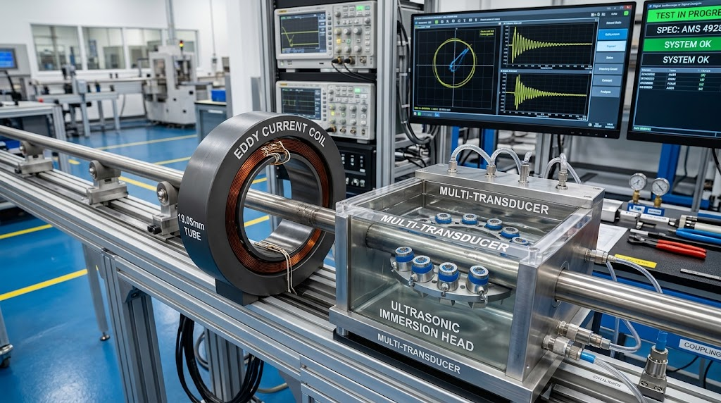
Modern tubular QA protocols combine continuous, non-contact laser dimension profiling with multi-frequency electromagnetic inspection and multi-channel ultrasonic testing. These verification systems must be integrated directly into the mill production line, ensuring 100% full-length inspection from end to end.
Continuous Multi-Channel Ultrasonic (UT), Eddy Current & Laser Micrometer Profiling
High-speed automated production uses dual-axis (or tri-axis) non-contact laser scanning micrometers positioned immediately downstream of the cold-pilger mill or rotary straightener. These laser systems take up to 2,000 circumferential readings per second, generating real-time trend plots of outer diameter, circularity, and runout. If localized tool thermal expansion causes the OD to drift near the upper control limit, the mill's closed-loop control system automatically compensates to prevent out-of-tolerance runs.
Subsurface integrity and internal wall thickness variations are verified through dual-discipline non-destructive testing:
Eddy Current Testing (ASTM E426): 100% full-length inspection utilizing an encircling coil and differential probe array. Calibrated against a primary standard tube containing radial through-drilled holes (diameter ≤ 0.8 mm) to detect pinholes, surface laps, and cracking across the outer diameter and inner bore.
Rotary Immersion Ultrasonic Testing (ASTM E213 / AMS 2631 Class AA/A): Conducted across 8 independent piezoelectric channels (4 transverse directions for longitudinal flaw detection, 2 longitudinal directions for circumferential cracks, and 2 normal incident beams for continuous wall thickness and eccentricity profiling).
Calibration Standard: Reference tubes must contain longitudinal and transverse Electro-Discharge Machined (EDM) notches on both the OD and ID surfaces. The maximum allowable notch depth is 10% of nominal wall thickness or 0.102 mm (0.004 in.), whichever is smaller, with notch length ≤ 3.18 mm and width ≤ 0.25 mm.
Every tube that passes through the ultrasonic immersion tank produces an automated inspection log detailing continuous minimum wall thickness, maximum wall thickness, and total wall eccentricity across its full length. Any tube exhibiting a localized flaw signal exceeding the reference notch threshold is automatically routed to a quarantine station for evaluation.
Alpha-Case Descaling, Acid Pickling Allowances & Hydrogen Pickup Taboos
A critical failure mode in titanium tube manufacturing occurs when mills attempt to correct over-tolerance outer diameters or heavy wall thicknesses through prolonged acid pickling. When titanium is annealed in atmosphere or an imperfect vacuum, interstitial oxygen and nitrogen diffuse into the surface, forming a hard, brittle, alpha-stabilized surface layer known as alpha-case.
To prevent alpha-case formation, high-grade titanium tubes must be annealed in cold-wall vacuum furnaces operating at high vacuum (ultimate pressure ≤ 10⁻⁴ Pa / 10⁻⁶ mbar) at temperatures between 650°C and 720°C, followed by inert gas argon cooling. If minor thermal oxide films form during hot operations, they must be removed via controlled pickling in a hydrofluoric and nitric acid solution (HF/HNO3).
The Operational Boundary & Hydrogen Embrittlement Limit: The normal pickling metal removal allowance is strictly restricted to 0.02 mm to 0.05 mm (0.0008 in. to 0.002 in.) per surface. The acid bath chemistry must be carefully controlled:
Acid Bath Taboo: If the nitric acid concentration drops below the 10:1 ratio, the solution can generate active nascent hydrogen that absorbs directly into the titanium crystal lattice. Using an aggressive acid bath to chemically strip an oversized tube (e.g., removing > 0.08 mm of wall thickness) leads to rapid hydrogen pickup. This causes bulk interstitial hydrogen concentrations to exceed the ASTM B338 upper limit of 0.015 wt% (150 ppm), producing internal titanium hydride needles that severely embrittle the tube wall and cause premature failure under low-stress bending or hydrotesting.
Following pickling, the tube surface is neutralized, thoroughly warm-water rinsed, and dried. The resulting outer and inner surfaces should exhibit a uniform, matte-silver finish with a surface roughness of Ra ≤ 0.4 μm to 0.8 μm (16 to 32 μin.), ensuring proper fluid flow properties and clean seating during roller expansion.
Procurement Checklist: Specifying Custom Tolerances on Purchase Orders & EN 10204 3.1 MTCs
Standard commercial purchase orders that simply reference "Grade 2 Titanium Tube per ASTM B338" leave critical parameters to default manufacturer interpretations. To prevent production delays, fit-up issues, or billing discrepancies, procurement teams should use a structured specification line item. Below is an engineering template designed to lock in necessary tolerances, testing parameters, and documentation requirements:
COMMODITY: Cold-Pilgered Seamless Titanium Alloy Tubing
STANDARD: ASTM B338 / ASME SB-338 (Latest Revision), TEMA Class R Compliant
GRADE: ASTM Grade 2 (UNS R50400), Triple VAR Melted, 100% Virgin Sponge Origin
DIMENSIONS: 25.40 mm OD (+0.05 mm / -0.05 mm) × 1.24 mm WT (Minimum Wall: +10% / -0%) × 6096 mm L (+1.0 mm / -0 mm)
GEOMETRY: Wall Eccentricity ≤ 6.0%; Out-of-Roundness (Ovality) ≤ 0.10 mm max; Straightness ≤ 0.6 mm per 1000 mm
HEAT TREATMENT: Vacuum Annealed (≤ 10⁻⁴ Pa) at 680°C ± 10°C; Zero Alpha-Case Permitted
SURFACE CONDITION: Pickled & Passivated (HNO3:HF ≥ 10:1); Hydrogen content ≤ 80 ppm; Surface roughness Ra ≤ 0.6 μm ID/OD
NDT & METROLOGY: 100% Full-Length ASTM E426 Eddy Current + 100% ASTM E213 8-Channel Ultrasonic (EDM Notch Depth ≤ 0.08 mm)
PRESSURE TEST: Hydrostatic Test at 17.5 MPa (2500 psi) holding for 10 seconds + Pneumatic Underwater at 1.7 MPa
DOCUMENTATION: Inspection Certificate per EN 10204 Type 3.1 detailing heat chemistry, interstitial H/O/N/C, mechanical tests (tensile, flattening, flaring), and continuous UT wall scan log.
When auditing incoming EN 10204 3.1 Mill Test Certificates (MTCs), Quality Assurance inspectors should systematically cross-reference the following five data points:
Ingot Melt Tracking: Verify the double or triple Vacuum Arc Remelting (VAR) furnace heat number to confirm the absence of uncontrolled, non-aerospace scrap feed.
Interstitial Chemical Conformance: Confirm carbon (C ≤ 0.08%), iron (Fe ≤ 0.25% for Gr 2, Fe ≤ 0.30% for Gr 12), nitrogen (N ≤ 0.03%), oxygen (O ≤ 0.18%–0.20%), and specifically hydrogen (H ≤ 0.015% / 150 ppm max; target < 80 ppm).
Specimen Testing Dimensions: Confirm that tensile test pieces follow ASTM E8 / E8M sub-size tubular or longitudinal strip geometries, and verify that the Flattening Test height factor e complies with the designated grade.
NDT Calibration Records: Verify the EDM notch calibration dimensions cited on the NDT certification report for compliance with ASTM E213.
Packaging Protections: Confirm that tubes are supplied with low-density polyethylene (LDPE) end caps, individually wrapped in polyethylene sleeves, and packed within ISPM 15 heat-treated, fumigated timber cases lined with desiccant packs.
Technical FAQ: Resolving Titanium Tube Tolerance & Fit-Up Engineering Challenges
Why does my ASTM B338 Minimum Wall tube weigh approximately 9% more than the standard theoretical catalog weight?
Catalog weight tables are calculated assuming nominal dimensions under an Average Wall (±10% WT) specification. When a purchase order specifies "Minimum Wall" (+20% / -0%), the manufacturer cannot roll to the nominal wall baseline without risking negative-tolerance non-conformance. Consequently, the mill shifts its cold-pilgering setup targets upward by +8% to +10% above nominal. Because titanium pricing is based on billed mass (kg or lbs), this setup adjustment results in an 8% to 10% increase in linear weight and final invoice cost. This additional cost can be mitigated by specifying a tighter precision pilgering band (such as +8% / -0% or +5% / -0%).
Can seamless cold-pilgered Grade 9 titanium tubes match the ±5% wall uniformity of welded Grade 2 strip tubes?
Yes. While standard seamless cold drawing yields a wall thickness variation of ±10%, modern 3-roll Long-Die (LD) cold-pilgering achieves wall thickness tolerances of ±5% on alloyed Grade 9 (Ti-3Al-2.5V) tubing. The 3-roll pilgering process applies continuous compressive radial forces against a precision-tapered carbide mandrel, redistributing the wall mass and eliminating the helical wall drift common in rotary pierced seamless hollows. This produces a wall cross-section that matches the uniformity of cold-rolled strip, without requiring a longitudinal weld seam.
How do we prevent excessive ovality and wall thinning in the bend zone of U-bent heat exchanger tubes?
During cold U-bending (governed by ASTM B338 Section 13 and TEMA RCB-2.31), the outer bend fiber (extrados) undergoes tensile stretching, resulting in wall thinning, while the inner fiber (intrados) undergoes compressive thickening. To limit wall thinning to ≤ 15% and ovality to ≤ 8% across tight bend radii (R ≤ 2.0 × OD), bending should be performed on a CNC rotary-draw bender equipped with an internal multi-ball mandrel and a counter-acting pressure die boost system. Following bending, the U-bends (along with at least 150 mm of adjacent straight leg) must undergo localized vacuum stress-relief annealing at 650°C to eliminate residual bending stresses, verify straight-leg parallel pitch, and ensure proper bundle insertion.
What causes orbital TIG weld root concavity when joining two ASTM B338 tubes from different heat lots?
Orbital weld root concavity (or suck-back) typically stems from two root causes: wall step mismatch (eccentricity) and variations in cast-to-cast trace chemistry. When the wall thickness step between adjoining tubes exceeds 0.10 mm (due to high wall eccentricity), the arc energy dissipates unevenly across the joint, causing premature collapse of the thinner wall. In addition, minor variations in trace elements (such as sulfur or oxygen content) between different mill heats can reverse the Marangoni fluid flow in the molten weld pool. This reversal pulls the molten root bead inward toward the high-surface-tension zone, creating internal root concavity. To prevent this, tube ends should be selected with matched wall thicknesses within ±0.03 mm, and the joint gap should be held to ≤ 0.05 mm.
Related Technical Specifications & Material Grade Hub — Engineering Consultation & Custom Tolerance RFQ
Selecting the proper titanium tubular product requires matching dimensional tolerance bands with environmental service parameters, allowable operating stresses, and corrosion margins. The engineering hub matrix below outlines recommended tubular product grades and standard delivery limits for industrial procurement:
| Product Category & Grade | Standard Dimensional Delivery Scope | Core Industrial Application Fit | Recommended Product Gateway |
|---|---|---|---|
| Titanium Grade 2 Tubing (UNS R50400 / CP Grade 2) | OD 6.0 mm to 88.9 mm WT 0.5 mm to 4.0 mm | TEMA shell-and-tube exchangers, marine cooling bundles, desalination plants | Grade 2 Tube Spec Sheet |
| Titanium Grade 9 Tubing (UNS R56320 / Ti-3Al-2.5V) | OD 3.18 mm to 38.1 mm WT 0.4 mm to 2.5 mm | Aerospace 34.5 MPa hydraulics, motorsport fuel rails, subsea risers | Grade 9 Aerospace Tubing |
| Titanium Grade 12 Tubing (UNS R53400 / Ti-0.3Mo-0.8Ni) | OD 12.7 mm to 76.2 mm WT 0.8 mm to 5.0 mm | High-temperature brine evaporators, sour gas coolers, petrochemical service | Grade 12 Tubing Specs |
| ASTM B861 Seamless Pipe (NPS Schedules 10S to 80S) | 1/4 in. NPS to 12 in. NPS Schedules 5S, 10S, 40S, 80S | Chemical process piping, offshore header spools, refinery transport lines | B861 Pipe Dimension Hub |
Technical Consultation & Mill Test Certificate (MTC) Requests
China Titanium Factory works with quality control managers, pipeline engineers, and heat transfer specialists to optimize tube bundles, resolve field fit-up challenges, and maintain custom dimensional tolerances. Our cold-pilgering facilities provide:
Step 1: Technical Drawing & Specification Review — Submit 2D/3D component drawings (STEP, DWG, PDF) along with operational parameters, specifying critical outer diameter, inner diameter, wall thickness, and straightness requirements.
Step 2: DFM Engineering Analysis & QA Dossier — Our engineering team provides a detailed 12-hour Design for Manufacturability (DFM) assessment, theoretical weight optimization review, and sample EN 10204 3.1 Mill Test Certificates and ultrasonic inspection logs from current production heats.
Step 3: Direct Metallurgical Consultation — Schedule a direct technical consultation with our Chief Cold-Pilgering Metallurgist to finalize ring-gage tolerances, review flattening test criteria, and confirm ISPM 15 seaworthy packaging and delivery schedules.
Contact the China Titanium Factory Engineering Desk: engineering@chinatitaniumfactory.com | Production Facility: Baoji Industrial Hi-Tech Development Zone, Shaanxi, China.