


















How to Specify Titanium Tubing for Shell-and-Tube Heat Exchangers: ASTM B338, TEMA Rolling & Failure Prevention
Procuring tubular products for mission-critical thermal equipment demands a precise understanding of physical metallurgy, code compliance, and mechanical fabrication dynamics. In desalination, offshore oil and gas, petrochemical refining, and power generation, shell-and-tube heat exchangers operate under aggressive fluid chemistry, cyclic thermal gradients, and crossflow velocities. Specifying titanium tube bundles requires balancing metallurgical purity, cold-work deformation limits, non-destructive examination (NDE) sensitivity, and joint rolling physics. Overlooking wall thickness definitions, interstitial element tolerances, or post-weld microstructural recrystallization leads directly to premature crevice corrosion, catastrophic acoustic resonance, or leaking tube-to-tubesheet roller-expanded joints.
To establish structural integrity and corrosion performance over decades of continuous operation, procurement engineers and thermal design specialists must transition from generic grade designations to rigorous, enforceable procurement clauses. Correctly defining parameters under ASTM B338 Seamless and Welded Titanium Heat Exchanger Tubes and ASME SB338 controls dimensional tolerances, yield-to-tensile ratios, hydrostatic test thresholds, and microstructural uniformity. Furthermore, integrating the Tubular Exchanger Manufacturers Association (TEMA 10th Edition) standards directly into purchase orders ensures that tube-to-tubesheet rolling geometries account for titanium's low elastic modulus and pronounced springback characteristics.
This technical guide establishes an empirical framework for specifying titanium tubing in shell-and-tube heat exchangers. It addresses the critical boundary conditions governing material selection, fabrication verification, quality assurance auditing, and installation. By implementing the manufacturing controls, testing mandates, and mechanical boundaries detailed below, engineering, procurement, and construction (EPC) teams and quality assurance managers can eliminate material failure modes and ensure absolute plant reliability.
Standard Differentiation: ASTM B338 Heat Transfer Tubing vs. ASTM B861/B862 Process Pipe
A frequent and costly procurement error in thermal equipment engineering is the conflation of heat transfer tubing with process piping. ASTM B338 / ASME SB338 covers seamless and welded titanium and titanium alloy tubes intended for surface condensers, evaporators, and heat exchangers. In contrast, ASTM B861 (seamless) and ASTM B862 (welded) cover nominal pipe size (NPS) structural and process fluid conduit. The fundamental engineering difference lies in diameter and wall thickness control: ASTM B338 governs exact Outside Diameter (OD) and specified wall thickness, whereas pipe specifications govern nominal sizing according to ASME B36.19M schedules, where outside diameter tolerances are wider and inner diameters vary with schedule wall thickness.
Heat exchanger mechanical design according to TEMA Class R, C, and B relies on diametral clearances between the tube outer surface and the tubesheet hole (typically drilled to TEMA standard or special close tolerances per TEMA Section 5, Table RCB-7.41). Workhorse heat transfer tubing sizing benchmarks are standardized around 19.05 mm (3/4 in.) and 25.4 mm (1 in.) OD, manufactured to Birmingham Wire Gauge (BWG) wall dimensions: BWG 18 (1.24 mm / 0.049 in.), BWG 20 (0.89 mm / 0.035 in.), and thin-wall BWG 22 (0.71 mm / 0.028 in.). Specifying process pipe under ASTM B861/B862 results in excessive diametral variations that violate TEMA roller expansion tolerances, preventing proper joint interlock or risking tubesheet ligament deformation.
| Parameter / Requirement | ASTM B338 / ASME SB338 (Exchanger Tubing) | ASTM B861 / ASTM B862 (Process Pipe) |
|---|---|---|
| Dimensional Control Metric | Exact Outside Diameter (OD) & Exact Wall (BWG/mm) | Nominal Pipe Size (NPS) & Schedule (e.g., Sch 10S, 40S) |
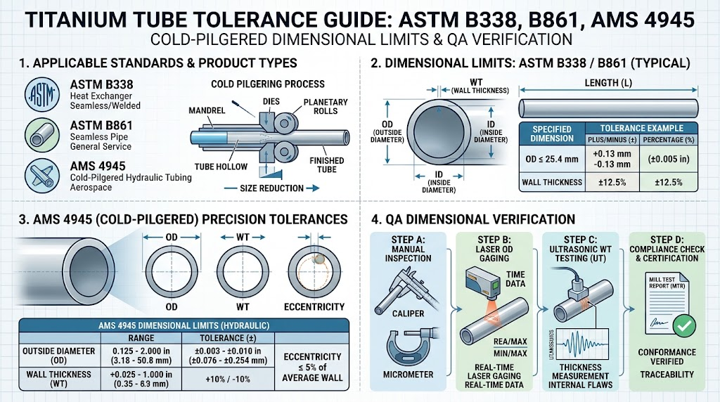
| OD Tolerance (19.05 mm – 25.4 mm) | ±0.10 mm (±0.004 in.) — tightly bounded | +0.40 mm / -0.80 mm — unsuitable for tight tubesheet drilling |
| Mandatory Mechanical Tests | Tensile, Flattening, Flaring, Reverse Flattening (WLD) | Tensile, Flattening, Bend test (sizes dependent) |
| Mandatory In-Line NDE | 100% Eddy Current (ASTM E426) or 100% Ultrasonic (ASTM E213) | Hydrostatic or non-destructive electric test (lot basis options) |
| Primary Intended Service | Conductive heat transfer; shell-and-tube and plate bundles | Bulk fluid transport, piping distribution, header manifolds |
Procurement documents must explicitly state whether wall thickness is ordered as Minimum Wall or Average Wall. When an engineer specifies 25.4 mm OD × 1.24 mm (BWG 18) as Minimum Wall, the manufacturer applies a unilateral tolerance (+20% / -0%), ensuring the absolute wall thickness never falls below 1.24 mm. If specified as Average Wall, the bilateral tolerance (typically ±10%) allows the wall thickness to measure as low as 1.116 mm. This difference changes the ASME Section VIII Division 1 internal pressure containment calculations (Formula UG-27) and external pressure bucking limits (Formulas UG-28 and UG-31), while also influencing extrusion parameters, raw material weight calculations, and mill delivery lead times.
Grade Selection & Corrosion Resistance Boundaries in Thermal Duty
Titanium provides exceptional corrosion resistance in heat exchanger service due to the spontaneous formation of a continuous, chemically stable, and adherent titanium dioxide (TiO₂) rutile/anatase passive film. This passive layer maintains thermodynamic stability across neutral, highly oxidizing, and moderately reducing aqueous environments containing high halide contents. However, process media variables—including temperature, localized chloride concentration, dissolved oxygen, and crevice geometry—dictate the metallurgical grade required for long-term service.
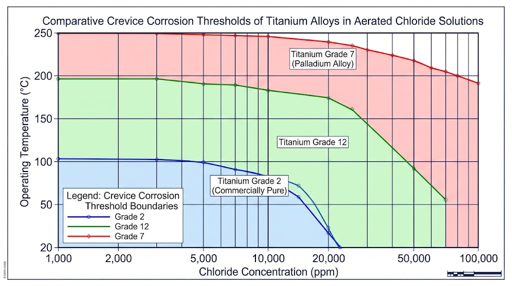
In thermal units operating in seawater, brackish cooling water, or hypersaline brines, the operational boundary is determined by localized tight-crevice corrosion. Although commercially pure titanium displays near-zero general corrosion rates (< 0.001 mm/year) in ambient seawater regardless of flow velocity, geometry-induced crevices (such as those under particulate sludge deposits or within the 0.05–0.15 mm tube-to-tubesheet joint interface) can experience de-oxygenation, localized acidification, and hydrolytic breakdown of the TiO₂ film when temperatures rise. Engineering specifications must follow established temperature and pH escalation pathways to avoid localized failure.
Grade 1 (UNS R50250) vs. Grade 2 (UNS R50400) for Seawater and Brackish Cooling Duty
Titanium Grade 2 (UNS R50400) Industrial Material Specifications represent the worldwide standard for industrial cooling duty, surface condensers, and MSF desalination plants. Grade 2 balances mechanical yield strength (minimum 275 MPa / 40 ksi) with sufficient ductility (minimum 20% elongation) to absorb roller-expansion deformation without micro-fissuring. Titanium Grade 1 (UNS R50250) is characterized by reduced interstitial elements (oxygen capped at 0.18% max, iron at 0.20% max), producing a softer matrix (minimum yield strength of 170 MPa / 25 ksi) with higher tensile elongation (≥ 24%).
While Grade 1 is advantageous for severe cold-drawing, complex plate-fin stamping, or heavy-gauge tubesheet roller expansion into deep-groove geometries, its lower allowable design stress under ASME Section VIII Division 1 (Table 1B) requires thicker wall sections to withstand identical internal or external design pressures. Grade 2 is therefore the standard selection for shell-and-tube exchangers handling cooling water at temperatures below 75°C–80°C (167°F–176°F). Its mechanical integrity, resistance to micro-fouling, and immunity to pitting attack by biological organisms make it a dependable alloy for power plant surface condensers.
| Element / Mechanical Metric | Grade 1 (UNS R50250) | Grade 2 (UNS R50400) | Grade 12 (UNS R53400) | Grade 7 (UNS R52400) |
|---|---|---|---|---|
| Carbon (C) max | 0.08% | 0.08% | 0.08% | 0.08% |
| Oxygen (O) max | 0.18% | 0.25% | 0.25% | 0.25% |
| Hydrogen (H) max | 0.015% | 0.015% | 0.015% | 0.015% |
| Nitrogen (N) max | 0.03% | 0.03% | 0.03% | 0.03% |
| Iron (Fe) max | 0.20% | 0.30% | 0.30% | 0.30% |
| Alloying Additions | None (CP Ti) | None (CP Ti) | 0.2–0.4% Mo, 0.6–0.9% Ni | 0.12–0.25% Pd |
| Tensile Strength Rm min | 240 MPa (35 ksi) | 345 MPa (50 ksi) | 483 MPa (70 ksi) | 345 MPa (50 ksi) |
| Yield Strength Rp0.2 min | 170 MPa (25 ksi) | 275 MPa (40 ksi) | 345 MPa (50 ksi) | 275 MPa (40 ksi) |
| Elongation in 2 in. (50 mm) min | 24% | 20% | 18% | 20% |
Grade Escalation Logic: Grade 12 (Ti-0.3Mo-0.8Ni) and Grade 7/16 (Ti-Pd) Above 80°C
When high-salinity fluids, crude distillation overhead fractions, or concentrated chemical brines operate above 80°C (176°F), Commercially Pure Grade 2 becomes vulnerable to crevice corrosion. The initiation mechanism involves the consumption of dissolved oxygen within microscopic, stagnant occluded geometries—such as the microscopic space between a tube's outer diameter and the tubesheet hole wall, or beneath mineral scaling. Depleted of oxygen, passive film repair stalls. Titanium cations hydrolyze, lowering localized crevice pH to < 2.0 while chloride ions migrate inward to preserve electroneutrality. This creates an aggressive hydrochloric acid environment that dissolves CP titanium along grain boundaries.
To prevent localized crevice attack, materials engineers specify Titanium Grade 7 (Ti-0.15Pd) and Grade 12 (Ti-0.3Mo-0.8Ni) Corrosion Resistant Alloys. Grade 12 (UNS R53400) is an engineered near-alpha alloy containing 0.3% Molybdenum and 0.8% Nickel. The nickel-rich intermetallic Ti₂Ni precipitates along grain boundaries, lowering the hydrogen overvoltage and providing cathodic polarization that stabilizes the TiO₂ passive film in mildly reducing, hot chloride environments. This shifts the crevice corrosion threshold up to approximately 150°C–175°C (302°F–347°F) across a broad pH range (pH 3–11), delivering a cost-effective alternative to palladium alloys in chemical process exchangers.
In high-temperature, low-pH applications reaching up to 250°C (482°F)—such as sour brine strippers, wet chlorine processing, and aggressive inorganic chloride reboilers—Grade 7 (UNS R52400) and its lean palladium alternative, Grade 16 (UNS R52402, containing 0.04%–0.08% Pd), are required. The metallurgical addition of palladium functions as an active cathodic depolarizer. By shifting the mixed corrosion potential noble to the active-passive transition potential, it sustains a stable TiO₂ passive film even in boiling, acidic chloride solutions (down to pH 1.0). When specifying welded tubes for such services, the seam must contain identical palladium or molybdenum/nickel fractions to prevent preferential weld fusion-line dissolution.
Operational Taboos & Tube-to-Tubesheet Galvanic Hydride Embrittlement
Despite its chemical stability, titanium exhibits specific operational boundaries that must be strictly observed in procurement and operating specifications. Titanium is rapidly attacked by anhydrous or aqueous hydrofluoric acid (HF) and acidic fluoride solutions; concentrations as low as 10 ppm of active fluoride ions dissolve the TiO₂ passive film, causing rapid general corrosion. Furthermore, titanium is prohibited in completely dry chlorine gas (< 0.5% moisture at ambient temperature; < 1.5% at elevated velocity/temperature). The absence of water molecules prevents passive film reformation, resulting in an exothermic reaction that can lead to pyrophoric combustion. Similarly, anhydrous red fuming nitric acid induces stress corrosion cracking (SCC) and explosive reactions unless at least 1.5% water is present.
A frequent failure mode in marine and process heat exchangers is tube-to-tubesheet galvanic coupling and associated titanium hydride embrittlement. When titanium tubes are expanded into tubesheets fabricated from electrochemically less noble metals—such as Naval Brass (UNS C46400), Muntz Metal (UNS C28000), Aluminum Bronze, or Carbon Steel—the large cathode-to-anode surface area ratio accelerates the corrosion of the tubesheet ligaments. When plant operators retroactively install sacrificial anodes or apply impressed-current cathodic protection (ICCP) systems to mitigate tubesheet loss, improper calibration can damage the titanium tubing.
If the polarized potential of the titanium tube ends drops more negative than -0.75 V relative to the Saturated Calomel Electrode (SCE), nascent atomic hydrogen evolves on the cathode surface. Below 80°C, the room-temperature diffusion rate of hydrogen into the alpha titanium lattice is low (hydrogen typically precipitates near the surface as harmless titanium hydride needles within a 10–20 μm skin). However, when metal temperatures exceed 80°C (176°F), the diffusion rate of interstitial hydrogen into the bulk matrix increases substantially. Once internal hydrogen levels exceed the solubility limit (~100–150 ppmw), brittle titanium hydride (TiH₂) phases precipitate along internal grain boundaries. This precipitation causes loss of ductility, wall cracking under roller-expansion stress, and spalling of tube ends during thermal cycling. Design specifications must cap ICCP potential between -0.50 V and -0.70 V vs. SCE, or mandate the use of solid or ASME SA263 / ASTM B265 Titanium Clad Tubesheet Plates to eliminate galvanic driving potentials entirely.
Manufacturing Route Specifications: Seamless (SMLS) vs. Welded & Cold-Worked (WLD)
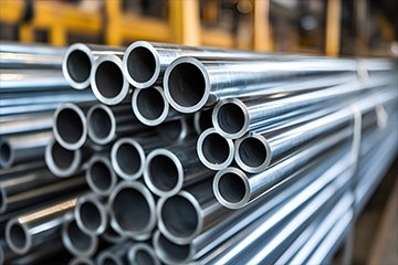
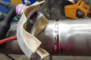
Under ASTM B338 / ASME SB338, engineers can specify two distinct manufacturing routes: Seamless (SMLS) or Welded (WLD). Seamless titanium tubes are produced from hollow extruded billets and cold-reduced via multi-pass cold pilgering (rocking) mills over tapered mandrels, followed by continuous vacuum or inert gas annealing. Welded tubing is manufactured from precision cold-rolled strip, continuously roll-formed into a tubular cross-section, and joined along the longitudinal seam using high-speed, non-consumable automatic Gas Tungsten Arc Welding (GTAW / TIG) or Plasma Arc Welding (PAW) under trailing and backing high-purity argon gas shields.
Welded and cold-worked titanium tubing has become the primary selection for power utility surface condensers, MSF desalination tubes, and intermediate-pressure chemical coolers. Modern laser and GTAW mills produce welded tubing with uniform wall thickness (±0.05 mm variance), consistent outer diameters, and competitive pricing (offering a 20% to 35% cost reduction relative to seamless alternatives). However, procurement documentation must explicitly distinguish between basic as-welded tubing and high-integrity welded-and-cold-worked tubing. If an engineer permits as-welded tubing that has undergone only light sizing and surface cosmetic dressing, the joint will retain an as-cast microstructure susceptible to failure under mechanical stress.
Seamless tubing remains the mandatory engineering choice for high-pressure exchangers (ASME Section VIII Div. 1 design pressures exceeding 5.0 MPa / 725 psi), cyclic thermal-hydraulic shock services, tight-radius U-bend applications (bend radius R < 2.0 × OD), and lethal process service (UW-2 designation). Seamless fabrication eliminates the metallurgical discontinuity of a longitudinal weld, preventing preferential attack in aggressive reducing acid environments where trace segregations at the weld seam can act as initiation sites.
Mandating Weld Bead Forging and Full Equiaxed Recrystallization on the PO
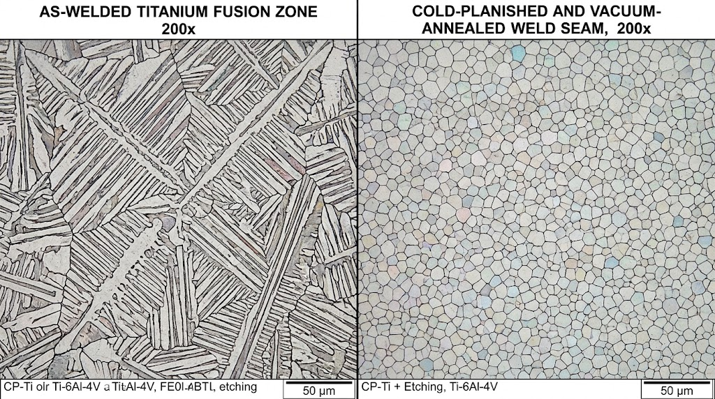
The primary metallurgical failure mode observed in basic welded titanium tubing during field assembly is cracking or flaking along the weld seam during TEMA roller expansion. As-welded titanium fusion zones consist of coarse, columnar, cast dendritic beta grains that transform into coarse acicular (Widmanstätten) alpha plates during cooling. This cast microstructure possesses low plastic strain capacity and lower ductility than the surrounding equiaxed, fine-grained alpha matrix of the parent strip. When subjected to 5% to 8% roller expansion wall thinning, severe localized shear stresses concentrate across the cast fusion boundary, generating micro-tears and weeping leaks.
To eliminate this failure mode, QA managers must insert a specific manufacturing requirement into the purchase order: "Welded tubes must undergo continuous inline weld-bead rolling (planishing/forging) or cold drawing, imparting a minimum of 15% to 20% plastic reduction across the weld seam, followed by protective atmosphere vacuum annealing to achieve 100% equiaxed grain recrystallization."
Applying mechanical cold deformation directly to the weld crown while supported by an internal mandrel breaks down the cast dendritic grain network. During the subsequent recrystallization anneal (conducted under vacuum at 650°C–720°C / 1202°F–1328°F), the stored energy drives complete nucleation of uniform, fine, equiaxed alpha grains (ASTM grain size No. 7 or finer). When properly executed, the fusion zone becomes metallurgically and mechanically uniform with the parent metal, eliminating variations in hardness, yield strength, and plastic flow behavior during rolling.
U-Tube Bending Thinning Limits & Vacuum Stress-Relief Annealing Protocols
U-tube bundles in shell-and-tube heat exchangers introduce geometrical and residual stress variables that require rigorous specification controls. When straight titanium tubes are cold-bent around a forming die, the outer fiber (extrados) undergoes tensile deformation, inducing wall thinning, while the inner fiber (intrados) undergoes compressive strain, causing localized thickening. Furthermore, the transverse cross-section at the bend apex distorts from a circular profile into an ellipse (ovality).
Engineering procurement specifications must define structural acceptance boundaries for bent sections:
Minimum Bend Radius: For Commercially Pure Grade 2, the minimum centerline bend radius must not fall below R = 1.5 × Tube OD (preferably R ≥ 2.0 × OD for high-pressure service) to prevent outer-fiber tearing.
Extrados Wall Thinning Limit: Extrados wall thinning must be calculated prior to forming using the established relationship:
Thinning Percentage (%) = [1 / (2 × (R / OD) + 1)] × 100 The Purchase Order must restrict final thinning such that actual wall thickness at the apex does not drop below the minimum required design thickness (tmin) determined by ASME BPVC Section VIII Div. 1, with an absolute maximum allowable thinning cap of 12% to 15% of nominal wall.Bend Ovality Control: Apex cross-sectional flattening (ovality) must be constrained to ≤ 6%, where ovality is evaluated as:
Ovality (%) = [(ODmax - ODmin) / ODnominal] × 100Mandatory Vacuum Stress-Relief Annealing: High residual tensile hoop stresses remaining in cold-formed U-bends present a significant risk of stress-accelerated corrosion. Specifications must require that all U-bends with a bend radius R ≤ 5 × OD undergo full vacuum stress-relief annealing (pressure < 1 × 10⁻⁴ mbar) or high-purity localized inert-argon resistance annealing at 540°C to 595°C (1004°F to 1103°F) with a minimum 30-minute dwell time. The heated zone must cover the complete 180° arc plus a minimum tangent length of 150 mm (6 in.) of the straight leg to prevent steep residual stress transitions at the tangent lines.
TEMA Mechanical Design & Tube-to-Tubesheet Joint Engineering
The mechanical performance of a shell-and-tube heat exchanger relies primarily on the integrity of the tube-to-tubesheet joint. In thermal exchangers, these joints must maintain a pressure seal and provide pullout strength under pressure thrust loads, structural dead weights, and cyclic differential thermal expansion between the bundle tubes and the shell. While design methodologies for conventional carbon steels, cupronickels, and austenitic stainless steels are mature, titanium exhibits unique mechanical properties that complicate standard fabrication practices.
Titanium possesses a low modulus of elasticity (Young's Modulus E ≈ 103–105 GPa / 15.0 × 10⁶ psi), which is roughly half that of carbon steel (200 GPa) or austenitic stainless steel (193 GPa). Additionally, titanium has a low Poisson's ratio (0.34) and a high yield strength relative to its modulus. Consequently, when a tube expander rolls a titanium tube outward into contact with the tubesheet hole, the tube matrix exhibits pronounced elastic springback upon roller retraction, altering the residual contact pressure required to maintain a seal.
Controlling Elastic Springback via Yield-to-Tensile Ratio and O/Fe Chemistry
Mechanical roller expansion relies on plastic deformation: the roller must strain the tube wall past its yield point and expand it against the tubesheet hole wall, subsequently expanding the surrounding tubesheet ligament within its elastic regime. When the rolling tool is removed, the elastic energy stored within the tubesheet ligament contracts onto the permanently deformed tube, creating an interfacial residual contact stress. However, if the tube material possesses a high yield-to-tensile ratio or significant work hardening, the tube springs back inward elastically away from the hole wall, compromising the joint's mechanical seal and pullout strength.
To avoid loose, weeping joints, procurement engineers must mandate tighter chemical and mechanical windows than the broad limits permitted by the standard ASTM B338 Grade 2 specification:
Yield-to-Tensile Ratio Control: The room-temperature Yield-to-Tensile ratio (Rp0.2 / Rm) must be strictly capped at ≤ 0.80, combined with a mandatory minimum tensile elongation of 24%. Tubes displaying yield strengths at the upper limit of the standard specification (> 400 MPa) will yield the tubesheet hole without adequate joint locking.
Interstitial Oxygen and Iron Restrictions: Interstitial oxygen dissolves in alpha-phase titanium as a potent solid-solution strengthener, raising yield strength while reducing cold formability. Iron accelerates work-hardening rates. Specifications should mandate:
Oxygen (O) Content: 0.12% to 0.18% max (do not permit the standard 0.25% ceiling)
Iron (Fe) Content: ≤ 0.12% to 0.15% max (do not permit the standard 0.30% ceiling)Roller Expansion Percentage: Apparent tube wall reduction during rolling must be calibrated to between 5% and 8% for titanium tubes seated into grooved tubesheets (incorporating two rectangular grooves, typically 3.2 mm wide × 0.4 mm deep). Rolling below 4% wall reduction results in insufficient contact stress, while over-rolling (> 10%) causes severe extrusion, micro-galling, and ligament distortion.
Joint Design Configuration: For operating pressures exceeding 2.0 MPa (290 psi), lethal service, or cyclic thermal differentials > 50°C, rolled-only joints are insufficient. Engineers must specify a strength-welded and lightly rolled or seal-welded and expanded joint configuration using automated, orbital pulsed-GTAW torches under complete chamber or trailing inert gas coverage (99.999% argon), followed by a light contact roller expansion 25 mm back from the tubesheet face to close the crevice and prevent vibration fatigue.
Auditing Baffle Spans & Young's Modulus Penalty in Thin-Wall Retubing
A frequent error encountered during refinery, chemical plant, and utility condenser revamps is the 1-to-1 material replacement of copper-nickel (90-10 or 70-30 Cu-Ni) or austenitic stainless steel (304L/316L) bundles with thin-wall titanium (BWG 22 / 0.71 mm or BWG 25 / 0.50 mm). Thermal-hydraulic engineers often justify this modification based on titanium's corrosion immunity and superior thermal conductivity compared to austenitic stainless steel, which allows for reduced tube wall thickness and lower bundle raw material weight.
However, implementing thin-wall titanium without re-evaluating the TEMA unsupported baffle span calculation (TEMA Section 5, Paragraph RCB-4) often leads to flow-induced vibration failure. Flexural tube rigidity is the mathematical product of the material's Modulus of Elasticity (E) and its cross-sectional Moment of Inertia (I):
Because titanium's elastic modulus is ~50% lower than that of stainless steel (103 GPa vs. 193–200 GPa), and because reducing wall thickness from BWG 16 (1.65 mm) to BWG 22 (0.71 mm) reduces the area moment of inertia, the flexural rigidity of the replacement titanium tube decreases substantially (often to less than 35% of the original bundle's rigidity). This drop lowers the tube's natural mechanical frequency (fn):
where m is the effective mass per unit length (accounting for metal, internal fluid, and shell-side added hydrodynamic mass) and L is the unsupported baffle span length.
Under shell-side crossflow, the lower natural frequency makes the tubes susceptible to Fluid-Elastic Instability (FEI), Vortex Shedding lock-in, and Acoustic Resonance at lower fluid crossflow velocities. This results in mid-span tube-to-tube collision, circumferential baffle cutting at support plates, and fatigue cracking at the tube-to-tubesheet joint interface. When re-tubing with thin-wall titanium, procurement teams must verify that the engineering audit includes: (1) recalculating maximum unsupported baffle spans per TEMA standards, (2) installing stake rods or intermediate anti-vibration strip baffles (AVBs) within window zones, or (3) selecting heavier wall gauges (BWG 18 or BWG 20) in the entrance impingement zones beneath shell inlet nozzles.
Non-Destructive Examination (NDE), Destructive QA & Seaworthy Export Logistics
Comprehensive Non-Destructive Examination (NDE) and verified quality assurance systems are critical when procuring titanium tubing for severe-service exchangers. A single through-wall micro-pinhole or weld lack-of-fusion defect in a bundle containing 5,000 tubes will contaminate process streams, force emergency shutdowns, and incur substantial production losses. Mill inspection mandates must go beyond standard visual and dimensional sampling by requiring full-length volumetric testing calibrated to tight flaw thresholds.
All titanium tubes manufactured for heat exchanger assembly under ASTM B338 must have 100% material traceability back to the primary raw sponge melt. The purchase specification must require double or triple Vacuum Arc Remelting (VAR) or Electron Beam Cold Hearth Melting (EBCHM) ingots to eliminate high-density inclusions (such as tungsten tool fragments or refractory metal carbide clusters) and low-density inclusions (interstitial-rich hard alpha defects). Chemical composition certificates, mechanical property reports, and non-destructive examination logs must be documented under EN 10204 3.1 Mill Test Certificates (MTC) or witnessed by an accredited third-party inspection agency (TPI) to EN 10204 3.2.
100% Dual-Method NDE (Eddy Current & Ultrasonic) Plus Hydrostatic/Pneumatic Leak Protocols
Modern QA procedures require dual-method inline non-destructive testing for heat exchanger tubing: combining high-speed Electromagnetic Eddy Current Testing (ET per ASTM E426) with full-coverage Ultrasonic Shear-Wave Examination (UT per ASTM E213). While eddy current testing detects surface and near-surface defects—such as longitudinally drawn scratches, laps, pits, and weld-line discontinuities—ultrasonic examination detects subsurface defects, lamination boundaries, and wall thickness variations within the metal matrix.
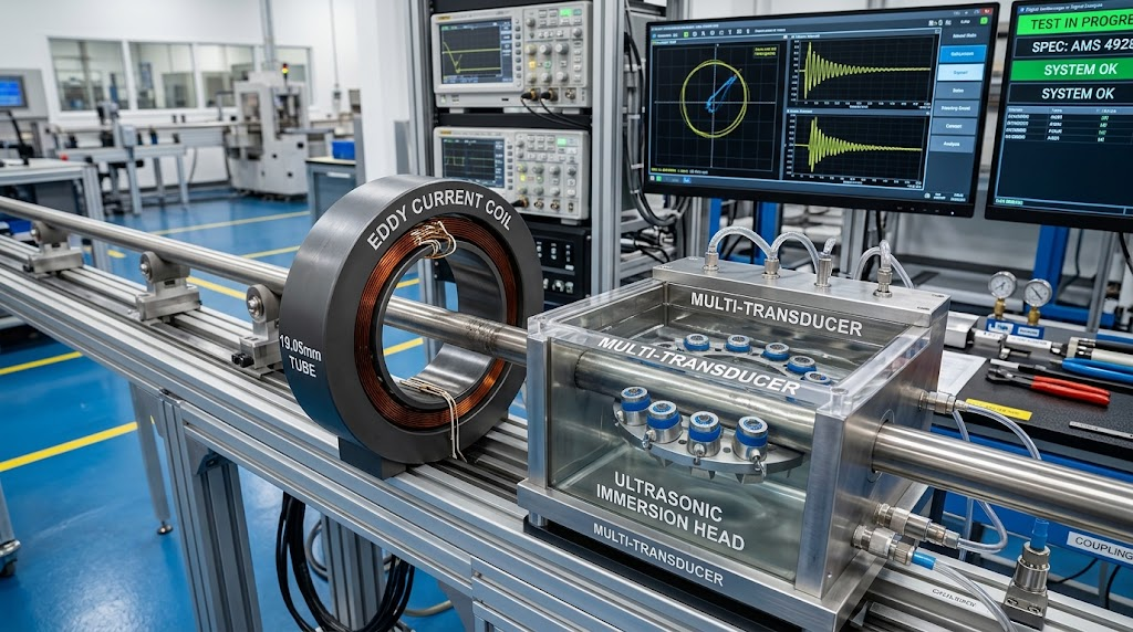
Calibration standards must be specified to tight, measurable reference notch tolerances:
ET Calibration: Calibrated using standard reference tubes containing transverse through-holes (maximum diameter 0.79 mm / 0.031 in.) and precision longitudinal outer-diameter/inner-diameter reference notches (notch depth ≤ 10% of nominal tube wall thickness, or 0.10 mm maximum; notch length ≤ 1.5 mm).
UT Calibration: Calibrated per ASTM E213 with longitudinal and transverse calibration notches on both inner and outer surfaces, with a maximum notch depth set at 10% of specified wall thickness (or 0.10 mm, whichever is smaller). Any tube triggering an echo signal exceeding the calibration threshold must be rejected.
Hydrostatic Proof Testing: Every individual tube must undergo factory hydrostatic testing per ASTM B338, maintaining test pressure for a minimum dwell period of 5 seconds without drop or leakage. The internal proof test pressure (P) must be mathematically calculated based on the maximum allowable fiber stress (S) set to 50% of the specified minimum yield strength:
P = (2 × S × t) / D where t is the specified wall thickness and D is the nominal tube outside diameter. The calculated pressure must not exceed 17.2 MPa (2,500 psi) unless specifically required by the EPC order.100% Underwater Pneumatic Testing: In addition to hydrostatic testing, every tube must undergo pneumatic bubble leak testing under demineralized water at a minimum clean, dry air/nitrogen pressure of 0.70 MPa (100 psi) for at least 5 to 10 seconds. Visual verification confirms the complete absence of pinhole bubble leakage along the longitudinal weld seam and the base tube body.
Destructive Lot Verification: From each manufacturing lot (maximum 1,500 meters or fraction thereof from the same heat and dimensional run), destructive sampling must include: longitudinal tensile testing per ASTM E8, flattening test per ASTM B338 (flattened between parallel plates to a distance H = (1 + e)t / (e + t/D)), flaring test using a 60° conical mandrel expanding the tube OD by a minimum of 15% (for Grade 2) without cracking, and reverse flattening tests applied specifically to the longitudinal weld seam.
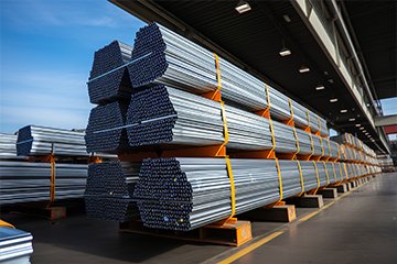
Seaworthy logistics packaging must protect the passive TiO₂ layer and maintain tube geometry during transport. Each individual titanium tube must be inserted into an extruded low-density polyethylene (LDPE) sleeve to prevent surface friction and galling. Tube ends must be sealed with clean, heavy-duty polyethylene push-in plugs to exclude airborne chlorides, road dust, and moisture. The bundle must be packed inside ISPM 15 fumigated, heat-treated wooden crates lined with heavy-gauge cross-laminated barrier film, complete with internal desiccant bags and fixed timber dividers to prevent sagging, bending, or ovality distortion during transit.
Technical Verification FAQ for EPC Procurement & QA Engineers
1. Can welded (WLD) ASTM B338 Grade 2 tubes be used in high-pressure or lethal ASME Section VIII Division 1 service, and how does the joint efficiency factor apply?
Yes, welded ASTM B338 Grade 2 tubes can be utilized under ASME Boiler and Pressure Vessel Code (BPVC) Section VIII Division 1. However, engineers must account for the longitudinal joint efficiency factor (E). Per ASME BPVC Section VIII Division 1, Table UW-12, an electric-resistance welded or automated TIG/plasma welded tube that complies fully with ASTM B338 (which includes mandatory full-length inline eddy current or ultrasonic volumetric inspection) can be assigned a joint efficiency factor of E = 0.85 in shell-and-tube mechanical pressure calculations. If the service is classified as "Lethal Service" per UW-2, designers must confirm whether the local jurisdictional code requires seamless (SMLS) construction, which carries a joint efficiency of E = 1.0 without weld inspection allowances. For standard petrochemical and utility exchangers, welded-and-cold-worked tubes meeting ASTM B338 provide an established, code-compliant baseline.
2. What is the maximum permissible iron content in ASTM B338 tubing when handling hot oxidizing brines?
While the standard ASTM B338 Grade 2 specification permits an iron content ceiling of up to 0.30 wt.%, this upper limit presents risks in hot oxidizing brines. Free iron in titanium can precipitate as brittle TiFe intermetallic phases along alpha grain boundaries if cooling rates are slow. These localized Fe-rich sites act as micro-cathodes that accelerate hydrogen evolution and cause localized galvanic micro-pitting in acidic, high-temperature brine systems. For critical thermal duties in desalination and chemical processing above 70°C, procurement specifications should impose a restrictive clause: "Residual Iron (Fe) content shall not exceed 0.12% to 0.15% max." Restricting iron preserves the uniformity of the protective TiO₂ passive film and reduces the risk of hydrogen entry into the metal matrix.
3. How do you prevent iron contamination on tube ends prior to orbital TIG tubesheet welding?
Iron contamination on titanium tube surfaces and weld preps is a frequent source of field weld porosity, cracking, and premature corrosion. When titanium comes into contact with carbon steel fabrication equipment—such as steel lifting wire ropes, carbon steel cutting blades, wire brushes, or grinding dust—metallic iron embeds mechanically into the relatively soft titanium surface. In contact with moisture, this embedded free iron oxidizes, disrupting the TiO₂ film and causing pitting. During welding, it melts into the weld puddle, causing embrittlement. Prevention requires dedicated stainless steel or rubber-lined handling equipment, non-metallic grinding wheels, and mandatory solvent cleaning. Following mechanical end-facing, tube ends must undergo acid pickling using a solution of 10%–20% Nitric Acid (HNO₃) and 1%–3% Hydrofluoric Acid (HF) by volume, followed by demineralized water rinsing to passivate the surface and eliminate trace contamination.
4. What specific documentation must be included in an EN 10204 3.2 third-party inspection dossier?
An EN 10204 Type 3.2 inspection dossier requires independent verification and dual-signing by both the mill's internal quality representative and an authorized, independent third-party inspection (TPI) surveyor (such as Lloyd's Register, TÜV Rheinland, SGS, or Bureau Veritas). The comprehensive dossier must contain: (1) Primary sponge batch certificates and double/triple VAR melting trace logs; (2) Ingot and finished product chemical analysis reports with direct inert gas fusion measurement of interstitials (H, O, N); (3) Longitudinal room-temperature tensile test data (Rm, Rp0.2, elongation); (4) Flattening, flaring, and reverse-flattening destructive test logs; (5) 100% Eddy Current and 100% Ultrasonic examination calibration strip charts; (6) Hydrostatic proof test charts indicating hold times and applied pressures; (7) Surface roughness (Ra) and wall thickness gauging dimensional logs; and (8) The TPI witness stamp verifying sample cutting and destructive test execution.
Related Technical Specifications & Material Grade Hub
To assist procurement engineers and thermal design specialists in developing comprehensive equipment bills of materials, the cross-reference matrix below links critical heat exchanger bundle components to their corresponding material grades, standard specifications, and operational envelopes.
| Material Grade & Specification | Primary Exchanger Component | Key Performance Metric | Thermal & Process Limit |
|---|---|---|---|
| ASTM B338 Seamless and Welded Titanium Heat Exchanger Tubes | Straight & U-tube heat transfer bundles | Rp0.2: 275–450 MPa; 100% dual NDE | Max continuous design temp: 315°C (600°F) |
| Titanium Grade 2 (UNS R50400) Industrial Material Specifications | Condenser tubing, tie rods, impingement plates | Balanced strength, ductility (A ≥ 20%) | Crevice corrosion threshold: ~80°C in brines |
| ASME SA263 / ASTM B265 Titanium Clad Tubesheet Plates | Explosion-bonded tubesheets (Gr. 2 on SA516-70) | Shear strength ≥ 140 MPa at bond line | Eliminates tube-to-tubesheet galvanic couples |
| Titanium Grade 7 (Ti-0.15Pd) and Grade 12 (Ti-0.3Mo-0.8Ni) Corrosion Resistant Alloys | Severe chemical service tubing & welded liners | High-temperature chloride crevice immunity | Up to 250°C (Gr. 7) / 175°C (Gr. 12) in low pH |
Technical Consultation & Mill Test Certificate (MTC) Requests
Procurement teams and EPC project engineers can interface directly with our metallurgical engineering staff to finalize equipment specifications, review design drawings, and audit material documentation. We provide a structured, engineering-driven qualification pathway:
Step 1: Specification & Drawing Review: Upload your heat exchanger bundle tube schedule, TEMA mechanical datasheet, or 3D CAD/DFM files (STEP, IGES, DWG) via our direct engineering portal.
Step 2: Engineering DFM & Quality Audit: Receive a detailed 12-hour Design for Manufacturability (DFM) review from our senior tubular mill engineers—including calculated U-bend extrados wall thinning rates, recommended Yield-to-Tensile and O/Fe limits for roller expansion, and a verified sample EN 10204 3.1 Mill Test Certificate (MTC) package.
Step 3: Direct Technical Consultation: Participate in a technical video conference with our metallurgical team and QA directors to align on ASTM E426/E213 NDE calibration defect thresholds, third-party inspection (TPI) witness milestones, and export packaging specifications.
China Titanium Factory maintains end-to-end process control from raw sponge selection and double Vacuum Arc Remelting (VAR) to precision cold-pilgering, automated inline weld planishing, vacuum recrystallization annealing, and certified dual-method non-destructive examination.