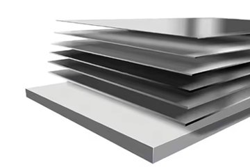
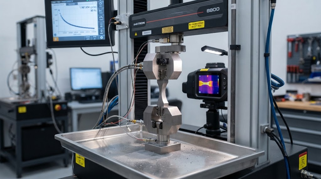
Titanium coil stamping springback control requires balancing the metal's low Young's modulus (105 to 115 GPa) against its high yield-to-tensile ratio. This mechanical profile stores significant elastic strain during deformation, releasing up to three times more angular elastic recovery upon die release than low-carbon steels. Achieving deterministic tolerances demands finite element overbend morphing, strict planar anisotropy management, and bottom dead center calibration across every progressive die station.
In conventional sheet metal forming, toolmakers rely on standard overbending charts developed for structural steel or austenitic stainless alloys. Applying these baseline equations to cold forming titanium strip results in immediate out-of-tolerance rejects. Titanium behaves fundamentally differently due to its hexagonal close-packed (HCP) crystallographic structure, which limits active slip systems at room temperature.

The fundamental physical driver behind elastic recovery is governed by the yield strength to modulus ratio (Rp0.2 / E). When bending stress is removed, the elastic strain component (εe = σ / E) unloads instantly along the elastic modulus slope, while plastic strain (εp) remains locked in the outer and inner fibers. Because titanium's elastic modulus is roughly half that of steel (105 GPa versus 210 GPa), its elastic strain recovery is double for an equivalent stress level.
"The springback factor Ks is defined as the ratio of the formed angle under punch load (θ0) to the final unconstrained part angle (θf). In titanium, Ks is rarely a scalar constant; it functions as an evolving tensor driven by true strain, instantaneous punch contact radii, and localized stress reversal under the Bauschinger effect."
The challenge escalates across material grades. When stamping commercially pure ASTM B265 Grade 2 titanium sheet and strip, yield strengths range between 275 and 350 MPa, resulting in moderate but highly direction-dependent springback. Moving to structural alpha-beta alloys like Grade 5 Ti-6Al-4V aerospace titanium coil, yield strength surges past 830 MPa while Young's modulus remains low (114 GPa), driving angular springback variations from 12° to over 25° on a nominal 90° bend.
| Material Specification | Young's Modulus (E, GPa) | Yield Strength (Rp0.2, MPa) | Tensile Strength (Rm, MPa) | Springback Ratio Index (Rp0.2 / E × 103) |
|---|---|---|---|---|
| Deep Draw Steel (DC04) | 210 | 180 | 310 | 0.86 |
| AISI 304 Stainless Steel | 193 | 290 | 620 | 1.50 |
| CP Grade 1 Titanium (ASTM B265) | 105 | 220 | 340 | 2.10 |
| CP Grade 2 Titanium (ASTM B265) | 105 | 310 | 450 | 2.95 |
| Ti-6Al-4V Grade 5 (AMS 4911) | 114 | 880 | 950 | 7.72 |
The elastic recovery index demonstrated above clarifies why conventional toolmaking compensation logic collapses. Ti-6Al-4V Grade 5 exhibits an elastic strain recovery index nearly nine times greater than deep-drawing carbon steels. Progressive die tooling must actively accommodate this dimensional drift through geometric pre-compensation and structural strain management.
When running continuous feed lines instead of isolated cut blanks, engineers frequently discover that identical tooling geometry produces fluctuating bend angles. The source of this instability lies in dynamic residual strip stresses, localized temperature rises across progressive die stations, and planar anisotropy introduced during cold rolling passes at the mill.
Continuous coil stock carries mechanical planar anisotropy defined by Lankford plastic strain ratios (r-values) across three strategic directions relative to strip rolling: 0° (longitudinal), 45° (diagonal), and 90° (transverse). Hexagonal close-packed alpha titanium develops a strong split-basal crystallographic texture during cold reduction, orienting the basal {0001} poles approximately 30° to 40° away from the sheet normal toward the transverse direction.
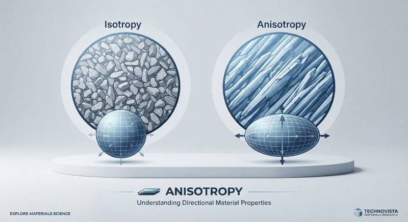
This crystallographic orientation creates significant variations in flow stress and elastic response depending on punch axis alignment:
Longitudinal Direction (0° to Rolling): Yield strength is typically 10% to 15% lower, with higher total elongation. Springback is moderate and more predictable.
Transverse Direction (90° to Rolling): Yield strength reaches maximum levels due to resistance against twinning and prism slip. Elastic recovery peaks here, driving maximum angular springback.
Diagonal Direction (45° to Rolling): Exhibits intermediate tensile properties but often experiences severe localized thinning and complex out-of-plane twist.
To quantify and manage this angular drift across thousands of continuous strokes, tooling engineers must use the Planar Anisotropy Coefficient (Δr):
Δr = (r0 - 2r45 + r90) / 2
When Δr deviates substantially from zero, bent parts experience out-of-plane torsional warping and sidewall curl. In high-speed progressive feeds, uncoiler back-tension fluctuations combine with continuous coil feed springback variables to shift the neutral axis during bending. Stabilizing progressive die output requires raw material processed under tight tension-leveling and cold-rolling controls to minimize Δr drift from coil lead to tail.
Controlling springback in multi-station tooling requires moving away from manual trial-and-error bench spotting. Die designers must use an integrated approach combining advanced finite element analysis (FEA) surface morphing, graduated overbending profiles, dynamic blank holder force (BHF) optimization, and Bottom Dead Center (BDC) coining.

Modern progressive die development relies on simulation solvers that calculate non-linear stress recovery based on anisotropic yield functions, such as the Barlat Yld2000-2d model. Once the unconstrained springback deviation vector is mapped in simulation, the tool surfaces undergo automated negative surface morphing.
If FEA predicts a positive angular springback of +3.8° along a formed channel sidewall with 0.8 mm outward bow, the punch and die cavity surfaces are morphed into an opposing -3.8° negative geometry featuring an inward crown compensation. This digital compensation eliminates weeks of manual press rework.
Die clearance and punch radius selection are decisive factors in controlling springback. When stamping commercial pure or alloy titanium strip, tool designers must adhere to specific proportional limits:
Punch Radius (Rp): Keep Rp as tight as the material's minimum bend radius allows without surface cracking. For Grade 2, target Rp = 1.0t to 1.5t. For annealed Grade 5, maintain Rp ≥ 4.0t for cold stamping to prevent tensile fracture on the outer fiber.
Die Entry Radius (Rd): Specify Rd between 4t and 6t to reduce sliding friction and prevent material galling.
Cutting & Forming Clearances: Maintain dynamic forming clearances between punch and die at exactly 1.05t to 1.08t. Tight gaps generate excessive frictional heating and premature galling; excessive clearances allow unchecked elastic unbending.
Pure air-bending of titanium generates unpredictable springback because the neutral axis retains an elastic core sandwiched between tensile and compressive yield zones. To neutralize this elastic core, progressive dies must incorporate a calibrated coining or restrike station directly at Bottom Dead Center.
Applying a controlled compressive through-thickness coin of 2% to 4% strip thickness directly at the bend radius forces the internal compressive stress state into uniform tensile plastic flow. This through-thickness stress equalization eliminates the internal bending moment responsible for springback, stabilizing the bend angle within ±0.25°.
While Commercially Pure (CP) titanium grades 1 and 2 stamp successfully at room temperature, complex geometries and higher-strength alloys like Grade 5 (Ti-6Al-4V) often demand elevated temperatures. Managing springback requires selecting the correct thermal window to reduce yield strength without inducing surface scaling or metallurgical degradation.
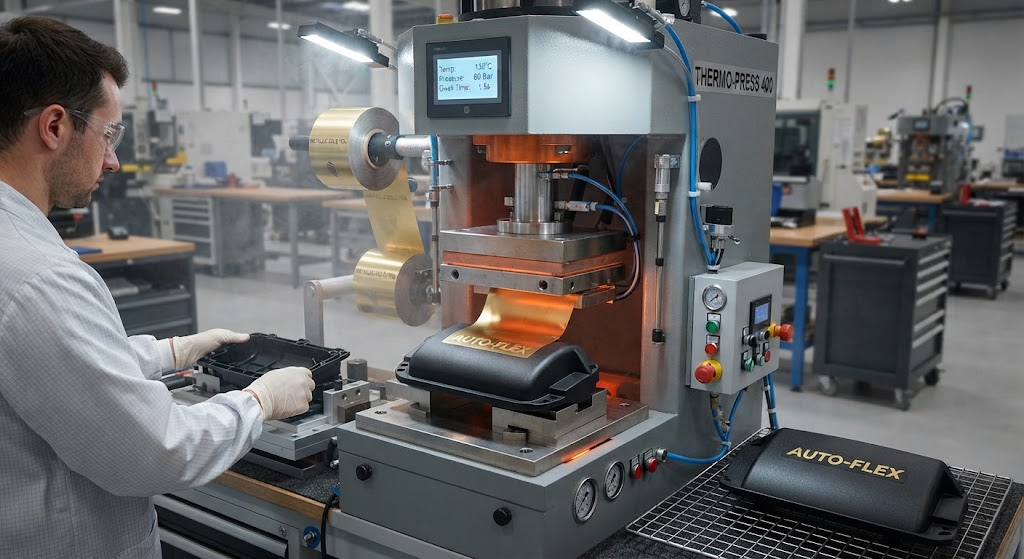
Forming temperatures fall into three distinct metallurgical regimes:
Cold forming is ideal for high-speed production of CP Grade 1, Grade 2, and Grade 11 strip. While cycle rates are high (60 to 120 strokes per minute), springback is elevated. Progressive tooling must integrate multi-stage overbend stations and bottom restrike coining to secure part tolerances.
Warm forming serves as the primary engineering solution for high-strength strip. Elevating strip temperature to between 200°C and 280°C activates additional pyramidal slip planes in the HCP alpha crystal lattice. This significantly reduces the yield-to-tensile ratio while lowering room-temperature yield strength by 25% to 40%.
Crucially, temperatures below 300°C prevent atmospheric oxygen and nitrogen pickup, avoiding brittle alpha-case formation and eliminating the need for post-stamping chemical milling or acid pickling. Tooling stations incorporate localized ceramic or induction cartridge heaters, allowing continuous progressive operation at 20 to 50 SPM with springback reductions exceeding 50%.
Reserved for complex, heavy-gage Grade 5 structural components, this process exploits thermal stress relaxation. Holding the formed blank in heated dies under hydraulic dwell allows stress to relax through microscopic creep mechanisms, virtually eliminating springback (yielding near-zero recovery). However, it operates as a low-volume batch process that demands vacuum or argon-purged environments and secondary chemical descaling.
| Thermal Regime | Target Temperature | Springback Reduction | Atmospheric Oxidation Risk | Tooling & Coating Requirements |
|---|---|---|---|---|
| Cold Stamping | Ambient (20°C - 50°C) | Baseline (0% reduction) | Zero risk | Tool steels (DC53, D2) with DLC or TiAlN PVD coatings |
| Progressive Warm Forming | 200°C - 280°C | 40% to 65% reduction | Negligible (No alpha-case formation) | Hot work tool steel (H13) with multi-layer CrAlN or AlCrN |
| Elevated Warm Forming | 300°C - 500°C | 65% to 85% reduction | Minor discoloration; no micro-cracking | High-temperature tool alloys; solid synthetic boron nitride lube |
| Hot Creep Sizing | 600°C - 750°C | 95% to 100% reduction | High; requires post-forming acid pickling | Cast nickel alloys (Inconel 718); ceramic thermal barriers |
Titanium displays a pronounced chemical affinity for iron under contact pressure, causing rapid cold-welding and tool galling. Galling damages stamped surfaces, shifts draw-in resistance, and disrupts calculated springback profiles. To counter this, progressive die stations must use Physical Vapor Deposition (PVD) hard coatings—primarily Chromium Aluminum Nitride (CrAlN) or diamond-like carbon (DLC)—paired with chlorinated or polymeric synthetic lubricants engineered for non-ferrous deep drawing.
Achieving a Process Capability Index (Cpk) exceeding 1.33 across hundreds of thousands of stamped titanium components requires integrating raw material cold-rolling controls with progressive tool execution. China Titanium Factory implements the proprietary Dual-Stage Strain Neutralization (DSSN) Protocol to close this process loop.
Engineering Insight: "Springback cannot be permanently stabilized in high-speed progressive tooling if raw material yield strength shifts by more than 15 MPa across a coil. Mechanical consistency at the mill establishes the baseline for part geometry."
The DSSN Protocol coordinates five distinct engineering phases across material fabrication and stamping execution:
Mill-Level Tension Leveling & Vacuum Stress Relief: Slit coil undergoes continuous stretch-tension leveling under tension-elongation control. This step flattens the strip and relieves internal longitudinal winding stresses. Coils are subsequently annealed in high-vacuum furnaces (10-4 mbar) to ensure complete recrystallization.
Equiaxed Microstructural Grain Refinement: Cold-reduction schedules are controlled to yield fine, equiaxed alpha grain structures conforming to ASTM E112 Grade 8 or finer. Fine grain morphology limits shear band localization and narrows the yield-to-tensile spread across the production run.
Directional Layout & Optical Anisotropy Mapping: Prior to tool progression layout, strip samples undergo optical tensile elongation testing across 0°, 45°, and 90°. Blank nesting in the progressive die is positioned to align critical bend radii precisely with the lowest-springback orientation.
Closed-Loop Progressive Warm-Station Integration: Tooling designs incorporate localized, temperature-regulated cartridge stations that heat the titanium strip to an optimized 220°C to 260°C window milliseconds before final draw, bend, and coining operations.
In-Line Continuous Laser Profilometry: Laser scanning profilers mounted at the tool discharge station monitor channel dimensions and flange angles in real time. These units feedback to micro-adjustable wedge blocks on the press restrike stations, correcting thermal and dimensional drift during continuous production.
Standard overbend compensation frequently fails in demanding applications characterized by ultra-thin gauges, elevated stroke speeds, or deep draws. The following industrial case studies demonstrate solutions applied to challenging production environments.
Proton Exchange Membrane (PEM) electrolyzers and fuel cells require stamping complex micro-channels (0.5 mm channel depth, 1.0 mm channel pitch) into 0.05 mm to 0.1 mm ultra-thin precision titanium strip and slit coil. The core challenge is preventing micro-channel buckling and localized channel height springback variations, which disrupt fuel distribution.
Using the DSSN framework, cold-rolled Grade 1 titanium strip is processed to an ASTM 9.5 grain size and run through micro-embossing dies with matched hydraulic counter-pressure. By maintaining thickness tolerances within ±0.003 mm and coining rib apexes at bottom dead center, channel height tolerances achieve ±0.015 mm across active areas exceeding 300 × 400 mm.
An aerospace customer required high-speed stamping of structural heat shims from 0.4 mm annealed Grade 5 (Ti-6Al-4V) strip at 80 strokes per minute, holding flange bend tolerances to ±0.25°. Standard cold stamping produced parts that opened by 14° to 19°, showing severe batch-to-batch variation.
The tooling was engineered using a three-stage progressive overbend: Station 1 bent the material to 75° (15° underbend); Station 2 formed it to 104° (14° overbend); Station 3 executed an in-line warm coining restrike at 240°C, compressing the inner radius by 3.2%. This multi-stage sequence stabilized final springback at a nominal 90.0° ± 0.18°, fully compliant with AMS 4911 aerospace specifications.
Implantable pacemaker and neuromodulation housings require deep drawing 0.3 mm CP Grade 1 strip into deep cups with draw-depth-to-width ratios exceeding 1.2:1. The primary challenge is sidewall wrinkle-and-flare springback along the open lip, which prevents automated hermetic laser welding.
By implementing multi-action nitrogen gas spring blank holders with zoned pressure pads, blank holder force (BHF) was dynamically regulated through the draw stroke. Applying an ironed lip restrike station eliminated sidewall flare, delivering an open-lip edge perpendicularity of 90° ± 0.20° compliant with ISO 5832-2 surgical implant standards without requiring secondary trimming.
Stabilizing high-volume progressive stamping depends directly on raw material consistency at the mill. As a fully integrated manufacturer, China Titanium Factory controls the complete production chain from vacuum-arc remelting (VAR) sponge titanium to finished slit coils and downstream precision stamping operations.
| Parameter | Manufacturing Scope & Tolerance Capabilities |
|---|---|
| Available Titanium Grades | CP Grade 1, Grade 2, Grade 3, Grade 4, Grade 7 (Ti-0.15Pd), Grade 9 (Ti-3Al-2.5V), Grade 11, Grade 12, Grade 5 (Ti-6Al-4V), Grade 23 (ELI) |
| Strip Thickness Range | 0.03 mm to 3.00 mm (0.0012" to 0.118") |
| Thickness Tolerance | Standard: ±0.010 mm; Precision Cold Rolled: ±0.003 mm to ±0.005 mm |
| Slit Coil Width Range | 10.0 mm to 1250 mm (Slitting width tolerance down to ±0.05 mm) |
| Edge Camber (Straightness) | < 1.0 mm per 1000 mm length (Precision Tension-Leveled) |
| Coil Inner Diameter (ID) | 300 mm, 400 mm, 505 mm (Steel core sleeves available upon request) |
| Surface Finish & Cleanliness | Bright Annealed (BA), Pickled (AP), Ra ≤ 0.2 μm, 100% degreased & lint-free |
| Compliance Standards | ASTM B265, ASME SB-265, AMS 4911, AMS 4902, ISO 5832-2, ISO 5832-3 |
| Quality Accreditations | AS9100D (Aerospace), ISO 13485 (Medical Devices), ISO 9001:2015, CE, PED 2014/68/EU |
| Inspection Documentation | EN 10204 3.1 Certified Mill Test Certificates; EN 10204 3.2 available via Third-Party Inspection (TUV, SGS) |
Our mill's 20-high Sendzimir cold-rolling mills achieve uniform strip thickness across the entire cross-section, eliminating the center-crown issues that compromise progressive die springback control. For customers requiring ready-to-assemble stamped components, our facility also operates in-house custom titanium precision stamping services, offering end-to-end quality assurance from raw ingot to finished stamped parts.
Cold stamping Grade 5 coil is mechanically feasible for generous geometries where the inner punch bend radius (R) is at least 4.5 to 5.0 times the material thickness (R/t ≥ 4.5), and blank shearing is free of micro-notches. However, cold springback under these conditions ranges from 15° to 25°, which introduces substantial process variation.
For tight-tolerance geometries (R/t < 3.0) and high repeatability, warm progressive forming between 220°C and 300°C is strongly recommended. This thermal window reduces springback by over 50% without risking alpha-case surface contamination, protecting dynamic fatigue life.
Springback drift across a single coil is caused by variations in yield strength and unreleased longitudinal winding tension. During coil rolling and batch annealing, thermal gradients can induce yield strength shifts of 30 to 45 MPa from outer wraps to the inner core. In titanium, a 30 MPa change in yield strength alters elastic recovery by up to 1.8° on a 90° bend.
China Titanium Factory prevents this drift by processing master coils through continuous tension leveling and continuous strand-annealing furnaces. This ensures yield strength uniformity within ±10 MPa across the entire coil length.
Because the transverse direction (90° to rolling) exhibits 10% to 15% higher yield strength and lower elongation than the longitudinal direction (0°), bending along the transverse axis generates the highest springback and carries greater cracking risk. When nesting blanks with complex, multi-axis bends, align the primary critical bends at 45° to the rolling direction to balance elongation capacity and springback stability.
Titanium readily galls against standard tool steels (such as untreated D2 or O1) due to solid-state microwelding under pressure. To eliminate galling, apply a comprehensive tooling strategy: build active die blocks from powder metallurgy steels (such as CPM 10V or DC53); mirror-polish punch and cavity radii to Ra < 0.1 μm; and coat working surfaces with high-adhesion PVD coatings like CrAlN or Diamond-Like Carbon (DLC). Pair this tooling with high-pressure synthetic forming lubricants containing polymeric extreme-pressure (EP) additives.
Eliminating springback defects in progressive titanium stamping requires aligning raw material processing with precision toolroom execution. Partner with China Titanium Factory through our structured three-step onboarding framework to optimize your production line:
Step 1: Submit Drawing & Specification Requirements
Send your 2D and 3D CAD files (STEP/IGES) alongside your material grade, annual part volumes, strip thickness limits, and geometric tolerance boundaries to our application team.
Step 2: Rapid Engineering DFM & Simulation Review
Within 24 hours, our engineering staff will provide a detailed Design for Manufacturability (DFM) assessment. This report includes non-linear FEA springback simulations, recommended forming temperature regimes, and tailored slit coil parameters (thickness tolerances, camber control, and edge conditioning).
Step 3: Direct Metallurgical Consultation & Pilot Validation
Collaborate directly with our Chief Tooling Engineer to finalize strip tension-leveling profiles, overbend surface parameters, and progressive die designs. We validate material performance using pilot prototype runs, guaranteeing a production capability of Cpk > 1.33.



Contact Us
Room 21003, 10th Floor, Unit 2, Building 1, Xianning International Plaza, No.29 Xianning West Road, Beilin District, Xi'an City
Copyright © Xi'an Shiguang Jingyan Technology Co., Ltd. All Rights Reserved.