






















Titanium Rod Straightness & Surface Finish Specifications: ASTM B348 Camber, ISO h6/h7 & Alpha-Case Removal
In precision machining environments, the geometric and metallurgical baseline established by standard mill delivery specifications presents a critical operational bottleneck. Standard specifications such as ASTM B348, ASME SB348, and AMS 4928 define broad physical and chemical envelopes suitable for generic forging and structural fabrications. However, when these materials are fed into high-speed CNC Swiss-type sliding headstock lathes, multi-axis mill-turn centers, or converted into fatigue-critical medical implants and aerospace actuation shafts, standard mill tolerances fail. Conventional hot-worked or cold-finished bars display bow camber, out-of-roundness, and surface conditions that lead directly to machine downtime, severe bar feeder harmonic whip, guide bushing galling, tool chipping, and unexpected post-machining component distortion.
Bridging this discrepancy requires a comprehensive understanding of dimensional metrology, cold-work residual stress profiles, centerless grinding kinetics, and elevated-temperature surface metallurgy. Titanium and its structural alloys—such as commercially pure Grade 2, Ti-6Al-4V (Grade 5), and extra-low interstitial Ti-6Al-4V ELI (Grade 23)—exhibit a uniquely low modulus of elasticity (approximately 105 to 115 GPa, nearly half that of structural steel) alongside high chemical affinity for atmospheric gases at processing temperatures. Consequently, unmachined mill bars often conceal both deep oxygen diffusion zones (alpha-case) and asymmetric residual stress fields generated during primary mill cross-roll straightening.
Meeting the rigorous processing windows of automated production lines requires moving past generic procurement orders. Engineers and procurement directors must transition from open commercial designations to tightly controlled technical callouts: quantifying camber through Total Indicator Reading (TIR) runout thresholds (≤ 0.25 mm/m to 0.50 mm/m), defining cylindrical surfaces by unilateral ISO 286-2 h-class tolerances with strict three-point lobing limits, mandating precise surface finish profiles (Ra and Rz), and enforcing mandatory radial stock removal depths to clear every trace of brittle alpha-case.
Dimensional & Straightness Tolerances by Manufacturing Process
The geometric precision of finished titanium round bar stock is fundamentally dictated by its thermo-mechanical processing history. In primary titanium mills, ingots synthesized via Vacuum Arc Remelting (VAR) or Electron Beam Cold Hearth Melting (EBCHM) are forged down to intermediate billets and subsequently hot-rolled into coils or straight bar lengths. As these bars transition across cooling beds from temperatures exceeding 750°C to ambient conditions, uneven radiative heat transfer, combined with phase transformations between beta and alpha microstructures, generates substantial longitudinal camber and cross-sectional warping.
Standard mill manufacturing routes employ multi-roll cross-axis rotary straighteners to bring hot-worked rods within the wide baseline envelopes dictated by commercial purchase specifications. However, the degree of geometric rectification achieved depends directly on the mechanical yield point of the alloy, the bar diameter, and the entry temperature during mechanical processing. High-strength alpha-beta alloys like Ti-6Al-4V Grade 5 exhibit significantly higher springback and resistance to plastic deformation than commercially pure unalloyed titanium (such as Grade 2). As a result, standard mechanical processing produces significant variations in straightness.
For high-precision downstream applications, procurement teams must evaluate straightness tolerance not as an arbitrary linear dimension, but as a function of the production route. The table below outlines how straightness degrades or tightens across different processing steps, contrasting basic industrial handling with specialized secondary sizing operations.
| Processing Route / Delivery State | Standard Governing Specification | Nominal Straightness (Camber Bow) | Typical Diameter Tolerance Band | Downstream Suitability & Limitations |
|---|---|---|---|---|
| Hot-Rolled, Descaled & Pickled | ASTM B348 Table 11 (Hot-Worked) | ≤ 4.17 mm/m (1/4 in. per 5 ft) | ± 0.40 mm to ± 1.20 mm | Forging stock, general structural hardware. Incompatible with standard collets or bar feeders. |
| Rotary Peeled / Rough Turned | ASTM B348 / AMS 4928 | ≤ 2.00 mm/m to 3.00 mm/m | +0.50 mm / -0.00 mm | Heavy conventional CNC lathe chucking; intermediate stock for final centerless grinding. |
| Cold-Drawn & Standard Straightened | ASTM B348 Table 11 (Cold-Finished) | ≤ 2.08 mm/m (1/8 in. per 5 ft) | h9 to h11 (ISO 286-2) | Low-RPM CNC turning (< 3,000 RPM). Moderate risk of bar feeder whipping over 2.5-meter lengths. |
| Precision Centerless Ground | Factory Standard / ISO h7 | ≤ 0.50 mm/m (TIR) | h7 (+0.000 / -0.015 mm typ.) | Automated bar-fed CNC screw machines, hydraulic spool valves, aerospace pins. |
| Ultra-Precision Medical Ground | ASTM F136 / ISO h6 Precision | ≤ 0.25 mm/m (TIR) | h6 (+0.000 / -0.009 mm typ.) | High-RPM Swiss sliding headstock turning (> 8,000 RPM); bone screws, spinal rods, dental implants. |
ASTM B348 Table 11 Camber Limits vs. Precision Swiss-Machining Straightness
The baseline standard for commercial titanium round bars, Aerospace & Industrial Titanium Bar Stock delivered under ASTM B348 / ASME SB348, contains a dedicated section governing geometric straightness: Table 11 (“Camber Tolerances for Titanium and Titanium Alloy Bar”). A critical review of Table 11 reveals allowable deviations that are unacceptable for modern precision CNC machining:
Hot-Worked Bars: Maximum camber of 1/4 inch in any 5 feet (equivalent to 6.35 mm per 1524 mm, or 4.17 mm per meter).
Cold-Finished Bars: Maximum camber of 1/8 inch in any 5 feet (equivalent to 3.18 mm per 1524 mm, or 2.08 mm per meter).
A major loophole in ASTM B348 Table 11 is the standard exclusion zone: camber measurements systematically exclude the extreme 150 mm (6 inches) at each end of the bar. During cross-roll straightening at the mill, the leading and trailing ends of the rod lose continuous three-point contact across the straightening rolls. This boundary condition causes severe end-hook or localized curvature within those unchecked 150 mm zones. If loaded into an automatic bar feeder, these hooked ends will immediately jam against the bar channel liner or crash into the machine guide bushing.
| Inspection Metric | ASTM B348 Table 11 (Hot) | ASTM B348 Table 11 (Cold) | CTF Standard Ground | CTF Precision Swiss | CTF Ultra-Precision Medical |
|---|---|---|---|---|---|
| Max Camber (per 1 m) | 4.17 mm | 2.08 mm | ≤ 1.00 mm | ≤ 0.50 mm | ≤ 0.25 mm |
| Max Camber (per 3 m Bar) | 12.51 mm | 6.24 mm | ≤ 3.00 mm | ≤ 1.50 mm | ≤ 0.75 mm |
| End Exclusion Zone | 150 mm excluded | 150 mm excluded | Zero (100% full length) | Zero (100% full length) | Zero (100% full length) |
| Max Recommended RPM | < 1,000 RPM | < 2,500 RPM | 4,500 RPM | 8,000 RPM | > 10,000 to 12,000 RPM |
For high-precision manufacturing, China Titanium Factory supersedes ASTM B348 Table 11 by performing supplementary two-roll precision hydraulic straightening followed by multi-pass centerless grinding. This yields guaranteed straightness levels down to ≤ 0.25 mm/m across the entire bar length, eliminating uninspected end-hook zones entirely.
Preventing Bar Feeder Whip & Guide Bushing Seizure in High-RPM CNC Swiss Lathes
In high-productivity Swiss-type screw machining (utilizing platforms such as Citizen-Cincom, Star, Tsugami, and Tornos), raw bar stock lengths of 3.0 meters (10 ft) or 3.66 meters (12 ft) are loaded into hydrodynamic oil-bath bar feeders. The spindle accelerates these rods to operational speeds between 6,000 and 12,000 RPM. Under these rotational velocities, dynamic instability is governed by centrifugal mechanics:
Fc = m · ω2 · e
Where m is the unit mass of the rod, ω is angular velocity, and e is the radial eccentricity (the straightness camber error). Because the outward centrifugal force scales quadratically with rotational speed (ω2), any slight residual bow camber triggers immediate harmonic whipping. A standard ASTM B348 cold-finished bar exhibiting a 2.0 mm/m bow generates violent lateral oscillations inside the feeder tube. This dynamic whipping produces critical operational failures:
Acoustic Resonance & Channelling Liner Wear: Severe hydrodynamic oil-film breakdown occurs inside the feed tube, causing physical collision between the titanium rod and polyurethane guide channels.
Guide Bushing Galling and Micro-Welding: Sliding headstock Swiss lathes rely on a static or synchronized rotary carbide guide bushing to support the bar stock radially against cutting tool pressures. Titanium exhibits severe adhesive galling tendencies when run against sintered tungsten carbide under high dynamic side-loads. If a whipping bar forces metal-to-metal boundary contact, localized friction creates micro-welds that instantly seize the bar within the bushing.
Surface Scoring: Even minor seizures scratch the incoming stock, causing rejects on cosmetic or fatigue-sensitive components such as dental abutments or aerospace hydraulic spools.
Preventing these failure modes requires strict raw material controls. First, diameter consistency must be held to Δd ≤ 0.005 mm along the entire 3000 mm length to maintain the critical 0.008 mm to 0.012 mm oil clearance within the carbide guide bushing. Second, incoming bar ends must feature a precise machine-chamfered lead-in (30° or 45° with all burrs removed) to eliminate collet-loading damage. Third, out-of-roundness (specifically odd-lobed three-point chatter) must be eliminated, as non-round cross sections disrupt the hydrostatic oil cushion inside the bushing, causing intermittent dry boundary friction and catastrophic seizure.
Total Indicator Reading (TIR) & Feeler Gauge Measurement Protocols on Granite Surface Plates
Verifying straightness requires precise metrology protocols. In production quality assurance, confusing camber per unit length with radial runout (Total Indicator Reading / TIR) creates significant inspection conflicts between mills and downstream QA auditors. China Titanium Factory implements two standardized inspection protocols depending on bar diameter and application criticality:
Protocol A: Granite Surface Plate & Precision Feeler Gauge (Camber Measurement)
The unconstrained titanium rod is degreased and positioned on a calibrated Grade AA laboratory granite surface plate (flatness verified within ± 0.002 mm per DIN 876/00). The rod is rotated manually through 360° until its natural concave bow arches upward, creating a maximum clearance gap between the granite reference surface and the underside of the bar. Certified, step-calibrated leaf feeler gauges (increments of 0.02 mm) are passed underneath the unsupported apex. The thickest gauge leaf passing freely without displacing the bar defines the maximum camber over that gauge length. This method isolates net structural curvature from localized diameter variations.
Protocol B: V-Block Support at Bessel Points with 0.001 mm Dial Runout (TIR Verification)
For precision ground shafts and Swiss-lathe stock, the rod is mounted on precision matched carbide-faced V-blocks positioned at the Bessel points (0.2203 × L from each end). This support geometry minimizes gravitational self-weight sagging during horizontal inspection. A calibrated digital indicator with 0.001 mm resolution is brought into contact with the top dead center of the bar. The rod is rotated through a continuous 360° cycle while the indicator is traversed along the linear axis. The peak-to-valley variance recorded is the Total Indicator Reading (TIR).
For a cylindrical rod exhibiting a uniform planar bow, the relationship between radial runout (TIR) and linear camber (gap clearance h) across a two-point supported span is defined as:
TIR = 2 · h
Procurement agreements must clearly state which parameter is being specified. Ordering a bar with “≤ 0.50 mm/m straightness” without stating the methodology invites ambiguity: if evaluated as camber under feeler gauge inspection, the gap is 0.50 mm, but if measured as Total Indicator Reading on V-blocks, the allowable radial envelope is cut in half (0.25 mm bow amplitude). China Titanium Factory standardizes all Swiss-machining bar inspection on Total Indicator Reading runout to ensure exact compliance with machine tool specifications.
Surface Finish Conditions, ISO Shaft Tolerances & Metallurgical Integrity
Surface topography and dimensional precision are inextricably linked to the structural integrity of high-performance titanium components. In dynamic service environments—such as orthopedic spinal rods, aircraft engine variable stator vane shafts, or offshore subsea fasteners—the surface of the rod serves as the primary initiation site for mechanical fatigue cracking, stress corrosion cracking (SCC), and hydrogen embrittlement. A smooth profile is not merely an aesthetic consideration; it is a primary engineering requirement.
Achieving reliable surface topography requires managing the interaction between titanium's physical properties and mechanical sizing equipment. Titanium's high chemical reactivity at elevated temperatures, combined with its propensity to gall against tooling steels, creates severe shearing and micro-tearing during cold operations. Achieving high-integrity finishes requires moving from rough hot-worked states through rotary peeling to precision multi-stage centerless abrasive grinding under flooded coolant systems.
Simultaneously, achieving tight cylindrical tolerances per ISO 286-2 requires precise machine kinematics. Diameter consistency, true circular runout, and the elimination of complex multi-lobed cross sections must be maintained along with microscopic surface finish targets. The following sections detail the quantitative metrics defining these engineering states.
Quantitative Surface Roughness Matrix: Pickled, Rotary Peeled, Centerless Ground & Polished (Ra / Rz)
Subjective visual descriptors like “bright finish,” “smooth turned,” or “clean surface” are insufficient for precision engineering procurement. Surface topography must be quantitatively specified using calibrated contact stylus profilometers or white-light interferometry, tracking both Arithmetical Mean Roughness (Ra per ISO 4287 / ASME B46.1) and Average Maximum Peak-to-Valley Height (Rz). The table below replaces ambiguous visual terms with verifiable quantitative engineering limits.
| Surface Condition Designation | Manufacturing Production Method | Ra Roughness (μm / μin) | Rz Roughness (μm / μin) | Primary Industrial Applications |
|---|---|---|---|---|
| Hot-Rolled & Acid Pickled | Continuous hot rolling + HF/HNO3 descaling | Ra 3.2 – 6.3 μm (125 – 250 μin) | Rz 12.5 – 25.0 μm (500 – 1000 μin) | Raw forging billets, chemical processing racks, non-sealing structural frames. |
| Rotary Peeled / Rough Turned | Rotary multi-tool peeling head descaling | Ra 1.6 – 3.2 μm (63 – 125 μin) | Rz 6.3 – 12.5 μm (250 – 500 μin) | Feedstock for finish grinding; general CNC chucked turning; marine drive shafts. |
| Commercial Centerless Ground | Vitrified bond SiC grinding wheel passes | Ra 0.8 – 1.2 μm (32 – 48 μin) | Rz 3.2 – 5.0 μm (125 – 200 μin) | General aerospace fasteners, chemical pump shafts, high-tolerance mechanical pins. |
| Precision Ground (Swiss-Grade) | Multi-pass fine grit centerless grinding | Ra ≤ 0.4 – 0.8 μm (16 – 32 μin) | Rz ≤ 1.6 – 3.2 μm (63 – 125 μin) | Swiss CNC sliding headstock machining, orthopedic bone screws, aerospace actuation rods. |
| Centerless Ground & Polished | Precision grinding + micro-abrasive belt superfinish | Ra ≤ 0.1 – 0.2 μm (4 – 8 μin) | Rz ≤ 0.4 – 0.8 μm (16 – 32 μin) | Implantable cardiovascular mandrels, spinal rods, dynamic hydraulic piston seals. |
For dynamic fatigue applications, specifying Rz alongside Ra is essential. Ra is an arithmetic average that masks localized micro-notches; two surfaces can share an identical Ra of 0.4 μm while one exhibits an extreme Rz value of 3.2 μm due to single-pass abrasive wheel pull-out. These isolated surface fissures act as primary fatigue crack initiation sites. China Titanium Factory strictly limits Rz to ≤ 4 × Ra on all precision-ground bar lines.
ISO 286-2 Shaft Tolerance Classes (h6, h7, h8, h9) & Out-of-Roundness (Ovality / 3-Point Lobing)
Precision cylindrical applications require adherence to ISO 286-2 unilateral negative tolerance classes (“h-tolerances”), where the nominal dimension represents the absolute upper limit (tolerance deviation +0.000 mm) with the entire allowable zone extending downward into negative territory. Standardizing on h-tolerances ensures reliable clearance through collets, tool-holders, and guide bushings.
| Nominal Diameter Range (mm) | ISO h6 (μm) | ISO h7 (μm) | ISO h8 (μm) | ISO h9 (μm) | ISO h11 (μm) |
|---|---|---|---|---|---|
| > 3.0 to 6.0 mm | +0 / -8 μm | +0 / -12 μm | +0 / -18 μm | +0 / -30 μm | +0 / -75 μm |
| > 6.0 to 10.0 mm | +0 / -9 μm | +0 / -15 μm | +0 / -22 μm | +0 / -36 μm | +0 / -90 μm |
| > 10.0 to 18.0 mm | +0 / -11 μm | +0 / -18 μm | +0 / -27 μm | +0 / -43 μm | +0 / -110 μm |
| > 18.0 to 30.0 mm | +0 / -13 μm | +0 / -21 μm | +0 / -33 μm | +0 / -52 μm | +0 / -130 μm |
| > 30.0 to 50.0 mm | +0 / -16 μm | +0 / -25 μm | +0 / -39 μm | +0 / -62 μm | +0 / -160 μm |
| > 50.0 to 80.0 mm | +0 / -19 μm | +0 / -30 μm | +0 / -46 μm | +0 / -74 μm | +0 / -190 μm |
A common quality issue in centerless grinding is tri-lobed (three-point) out-of-roundness. Centerless grinders support the bar between a high-speed grinding wheel, a rubber-bonded regulating wheel, and an angled work-rest blade. If the blade angle or the work-center height above the wheel centerlines is improperly calibrated, the bar experiences periodic chatter. This generates an odd-lobed constant-breadth profile (a Reuleaux triangle cross-section).
Standard two-point anvil micrometers cannot detect three-point lobing because the diametral distance across opposing points remains constant around the circumference. When an inspector measures this bar with a hand micrometer, the diameter appears within the h6 envelope. However, when loaded into a three-jaw chuck or a rigid circular Swiss guide bushing, the triangular lobes bind and seize.
To prevent this condition, China Titanium Factory mandates continuous non-contact multi-axis laser micrometer profiling during production. For physical QA audits, bars are inspected in a precision 60° V-block using a calibrated dial gauge. Ovality, circular runout, and three-point lobing are capped at ≤ 50% of the total ISO tolerance zone (for example, no more than 0.0045 mm on an Ø 10.0 mm h6 bar).
Complete Removal of Brittle Alpha-Case: Mandatory Radial Machining Allowances
During thermo-mechanical processing—such as ingot breakdown, hot forging, and hot finish rolling—titanium alloys are exposed to atmospheric temperatures between 700°C and 1050°C. Under these conditions, titanium readily absorbs atmospheric interstitial elements, particularly oxygen and nitrogen. Oxygen acts as a potent alpha-phase stabilizer. As oxygen diffuses into the surface, it forms a brittle interstitial solid-solution layer known as the alpha-case.
The alpha-case layer displays high micro-hardness (> 450 to 600 HV, compared to 300–340 HV for a standard baseline Ti-6Al-4V core microstructure) paired with near-zero plastic ductility. Under dynamic fatigue or tensile loading, this brittle shell micro-cracks at low strain thresholds. These micro-cracks propagate into the ductile core, causing catastrophic early fatigue failures. Furthermore, alpha-case is extremely abrasive to cutting tools, rapidly chipping carbide inserts during CNC turning operations.
Acid pickling can remove light surface scales, but deep interstitial diffusion layers require physical machining. Procurement specifications must mandate sufficient radial stock removal to completely clear this oxygen-enriched layer. China Titanium Factory enforces the radial machining allowances detailed below, verifying removal per AMS 2642 metallographic etch protocols.
| Nominal Bar Diameter Range | Typical Alpha-Case Depth | Mandatory Radial Removal (per side) | Total Diametral Stock Allowance | Post-Machining Verification Standard |
|---|---|---|---|---|
| Ø 6.0 to 25.0 mm | 0.10 – 0.25 mm | ≥ 0.50 mm per side | ≥ 1.00 mm on OD | AMS 2642 / ASTM E384 Microhardness Traverse |
| > Ø 25.0 to 50.0 mm | 0.20 – 0.40 mm | ≥ 0.75 mm per side | ≥ 1.50 mm on OD | AMS 2642 Metallographic Etch Inspection |
| > Ø 50.0 to 100.0 mm | 0.35 – 0.60 mm | ≥ 1.00 mm per side | ≥ 2.00 mm on OD | 100% Macro-Etch & Dye Penetrant Check |
| > Ø 100.0 to 200.0 mm | 0.50 – 0.90 mm | ≥ 1.50 mm per side | ≥ 3.00 mm on OD | Kroll's Reagent Swab Test & Core Hardness Match |
Supplying round bars with zero residual alpha-case is verified using metallographic cross-sections mounted in bakelite, polished, and etched with Kroll's Reagent (2% HF, 4% HNO3, 94% H2O). Under optical microscopy at 200× to 500× magnification, fully peeled and ground stock reveals zero white-etching surface layers, with base material microhardness maintained right up to the outer diameter edge.
Operational Boundaries, Residual Stress Relief & Failure Prevention
While cold sizing, mechanical straightening, and centerless grinding yield tight geometric tolerances, they alter the material's internal stress state. Titanium alloys possess low thermal conductivity (~6.7 W/m·K for Grade 5, roughly one-eighth that of mild carbon steel) and low elastic modulus. These combined physical traits make titanium exceptionally sensitive to mechanical shock, localized thermal spikes, and severe residual stress accumulation.
If process parameters are not carefully controlled, finishing operations can introduce severe, unseen metallurgical failure modes. These range from delayed room-temperature cracking to catastrophic warping during subsequent CNC milling. The following sections outline the specific operational boundaries required to maintain geometric and structural stability throughout secondary processing.
Rotary Straightening Residual Stresses & CNC Machining Distortion (“The Banana Effect”)
Two-roll rotary straighteners operate by subjecting incoming curved rods to alternating, reverse-bending cycles under compressive radial loads. The surface of the bar is plastically yielded while the elastic inner core is forced into alignment. This mechanical deformation straightens the overall longitudinal axis. However, it locks high, self-equilibrating internal residual stress gradients into the cross section: high compressive stresses in the outer 0.5 mm to 1.5 mm skin balanced by tensile stresses across the core.
When this bar is subjected to symmetrical processing (such as uniform outer-diameter turning), the residual stress state remains balanced. However, when the stock undergoes asymmetric CNC machining operations—such as milling long keyway slots, cutting complex flutes, turning eccentric steps, or profiling medical bone plates—the outer compressive stress layer is removed on one side. This unbalances the internal stress distribution:
Δσresidual → Internal Bending Moment → Spontaneous Camber Warping
The bar instantly bows toward the machined side, a failure mode known across CNC machine shops as the “Banana Effect.” A shaft ground perfectly straight to ≤ 0.25 mm/m can bow by 1.5 mm to 3.0 mm over a 500 mm span immediately upon release from the machining fixture.
Eliminating this distortion requires inserting an intermediate thermal stress-relief anneal into the manufacturing sequence. The bar must undergo rotary straightening, followed by furnace stress relief, and then final precision centerless grinding. China Titanium Factory applies strict thermal stress-relief parameters:
Commercially Pure Titanium (Grades 1–4): Soak at 480°C to 540°C (900°F – 1000°F) for 60 to 90 minutes in vacuum or inert argon; air or inert furnace cool.
Alpha-Beta Titanium Alloys (Ti-6Al-4V Grade 5 & Grade 23 ELI): Soak at 540°C to 650°C (1000°F – 1200°F) for 60 to 120 minutes; vacuum furnace cool to ≤ 400°C, then inert gas purge.
This thermal cycle relaxes up to 90% of internal residual stresses through micro-creep mechanisms without initiating primary phase grain growth or altering tensile properties. Subsequent finish grinding (taking light passes of ≤ 0.02 mm) refines the outer dimensions within the specified ISO tolerance band without reintroducing residual stress.
Centerless Grinding Thermal Damage, Galling & Acid Pickling Hydrogen Limits
Secondary surface finishing operations introduce two distinct hazards that require rigorous operational control: localized thermal surface damage during grinding, and chemical hydrogen embrittlement during acid descaling.
Centerless Grinding Mechanics & Thermal Control: Because titanium exhibits low thermal conductivity, heat generated at the abrasive-metal contact zone does not dissipate into the bar core. Instead, friction temperatures can rapidly exceed 800°C. If standard aluminum oxide (Al2O3) wheels are run at conventional steel-grinding surface speeds (> 30 m/s), the titanium reacts with the abrasive grain, causing immediate wheel loading, severe galling, and “grinding burn.” Grinding burns generate localized surface re-hardening, micro-checking (hairline cracks), and high tensile skin stresses that degrade rotating fatigue life.
To prevent thermal grinding damage, China Titanium Factory maintains strict grinding parameters:
Abrasive Media: Green Silicon Carbide (SiC) wheels or premium cubic boron nitride (CBN) wheels with vitrified bonds that resist chemical attack from titanium.
Wheel Surface Speed: Kept at 15 to 20 m/s (roughly half the surface speed used for steel grinding).
High-Pressure Lubrication: Flooded water-soluble extreme-pressure (EP) coolants delivered directly to the wheel-workpiece contact zone via specialized high-velocity laminar nozzles to flush heat and swarf instantly.
Acid Pickling Stoichiometry & Hydrogen Embrittlement: Chemical descaling and etching utilize hydrofluoric-nitric acid baths (HF + HNO3). The primary chemical reaction involves hydrofluoric acid stripping surface oxides and metallic titanium:
2 Ti + 6 HF → 2 TiF3 + 3 H2↑
This reaction generates atomic hydrogen (H+). If the nitric acid (HNO3) concentration is depleted, atomic hydrogen diffuses rapidly into the interstitial spaces of the titanium crystal lattice. Upon reaching ambient temperatures, interstitial hydrogen precipitates as brittle titanium hydrides (TiH2), causing delayed catastrophic brittle fracture under sustained mechanical load.
Preventing hydrogen pickup requires rigorous chemical bath control:
Acid Stoichiometry: Nitric-to-hydrofluoric acid concentration must be maintained at a minimum ratio of 10:1 (e.g., 20–35% HNO3 by weight to 2–3.5% HF by weight). The nitric acid acts as an oxidizing passivator that minimizes the absorption of nascent atomic hydrogen.
Bath Temperature: Maintained strictly at ≤ 55°C (130°F). Elevated temperatures accelerate hydrogen diffusion rates into the metal core.
Maximum Hydrogen Thresholds: Raw materials must be verified via inert gas fusion analyzers (per ASTM E1447). Hydrogen content is kept strictly below 125 ppm (0.0125%) for aerospace (AMS 4928) and medical (ASTM F136) specifications, and below 150 ppm (0.0150%) for standard industrial service (ASTM B348).
Mandatory Purchase Order (PO) Callouts, NDT Verification & Export Packaging
Procuring titanium rod for high-yield precision applications requires comprehensive contract language. Generic purchase orders stating “1-inch Ti-6Al-4V round bar per ASTM B348” leave critical geometric and subsurface parameters open to mill interpretation. The mill fulfills the contract by shipping hot-rolled, cross-roll straightened material with up to 6.35 mm of camber, deep unmachined alpha-case, unchamfered ends, and loose outer-diameter tolerances.
To protect downstream production runs and avoid component rejections, QA managers and procurement directors must establish unambiguous contract parameters. Specifying exact ISO tolerance classes, Total Indicator Reading runout limits, mandatory thermal sequences, non-destructive testing gates, and export packaging ensures raw stock functions reliably upon delivery.
RFQ Parameter Matrix & Line-Item PO Templates for Aerospace (AMS 4928) & Medical (ASTM F136)
The translation matrix below outlines how each purchase order parameter directly governs shop-floor manufacturing reliability, highlighting the consequences of omitting specific callouts.
| RFQ Parameter Field | Exact Specification Requirement | Engineering Consequence if Omitted from PO |
|---|---|---|
| Straightness (TIR) | ≤ 0.25 mm/m to ≤ 0.50 mm/m TIR (full length) | Defaults to ASTM B348 Table 11 (≤ 2.08 to 4.17 mm/m), causing feeder whip and guide-bushing seizure. |
| Diameter Tolerance | ISO 286-2 h6 or h7 (+0.000 mm / negative tolerance) | Defaults to wide bilateral stock (+/- 0.4 mm); will not pass through fixed guide bushings or standard collets. |
| Surface Roughness | Centerless Ground: Ra ≤ 0.4 μm, Rz ≤ 1.6 μm max | Material arrives with rough-peeled or pickled bark (Ra > 3.2 μm), causing tool wear and seal leaks. |
| Thermal Sequence | Straightened + Stress-Relieved (SR) before grinding | Asymmetric CNC machining triggers the “banana effect,” warping finished parts out of tolerance. |
| End Preparation | Both ends machine chamfered: 30° × 1.5 mm, deburred | Abrasive saw-cut ends with burrs damage collets, tear feeder push-bushings, and fail auto-loading. |
| Alpha-Case Control | Zero Alpha-Case; verified via AMS 2642 metallographic etch | Brittle subsurface layers fracture under cyclic fatigue stress and chip carbide cutting inserts. |
# TEMPLATE A: Medical Implant Bone Screw & Spinal Rod Stock (Copy-Paste PO Text)
ITEM 01: Titanium Round Rod, Grade 23 ELI (Ti-6Al-4V ELI per ASTM F136 / ISO 5832-3).
DIMENSIONS: Nominal OD Ø 8.000 mm (+0.000 / -0.009 mm, ISO h6) × 3000 mm Length.
STRAIGHTNESS: ≤ 0.25 mm per meter Total Indicator Reading (TIR) verified on V-blocks across full length with zero end-exclusion allowance.
SURFACE FINISH: Precision Centerless Ground, Ra ≤ 0.40 μm (16 μin), Rz ≤ 1.60 μm. Free from longitudinal seams, laps, or grinding burns.
OUT-OF-ROUNDNESS: Ovality and 3-point lobing ≤ 0.004 mm (50% of h6 band) verified via 60° V-block dial gauge inspection.
THERMAL HISTORY: Ingot produced via Triple VAR. Vacuum stress-relief annealed (600°C ± 10°C for 90 min) post-straightening, prior to final finish grind.
END PREPARATION: Both ends chamfered 45° × 1.0 mm, faced 90° flat, burr-free for automatic CNC Swiss bar feeder engagement.
METALLURGY: Zero alpha-case per AMS 2642. Interstitial Hydrogen ≤ 0.010% (100 ppm) per ASTM E1447.
CERTIFICATION: EN 10204 3.1 MTC containing heat chemistry, tensile data per ASTM E8, transus temp, and ultrasonic scan per AMS 2631 Class AA.
# TEMPLATE B: Aerospace Hydraulic Actuator Shaft Stock (Copy-Paste PO Text)
ITEM 01: Titanium Round Bar, Grade 5 (Ti-6Al-4V per AMS 4928 / AMS 4965).
DIMENSIONS: Nominal OD Ø 25.400 mm (+0.000 / -0.021 mm, ISO h7) × 3660 mm Length.
STRAIGHTNESS: ≤ 0.50 mm per meter Total Indicator Reading (TIR) verified across 100% of length.
SURFACE FINISH: Fine Centerless Ground, Ra ≤ 0.80 μm (32 μin). 100% surface eddy-current inspected per ASTM E426.
THERMAL HISTORY: Double VAR melted. Annealed and thermally stress-relieved (620°C for 120 min) following rotary straightening.
DEFECT GATES: 100% Volumetric Ultrasonic Inspection per AMS 2631 Class AA (0.8 mm FBH equivalent) with zero acceptable loss of back reflection.
CERTIFICATION: EN 10204 3.1 MTC with melt-to-shipping lot traceability, macro-structure rating, and mechanical testing compliance.
Volumetric Ultrasonic (AMS 2631 Class AA), Eddy Current & Export Crating Safeguards
Before precision ground rods are packaged for dispatch, they pass three non-destructive inspection gates:
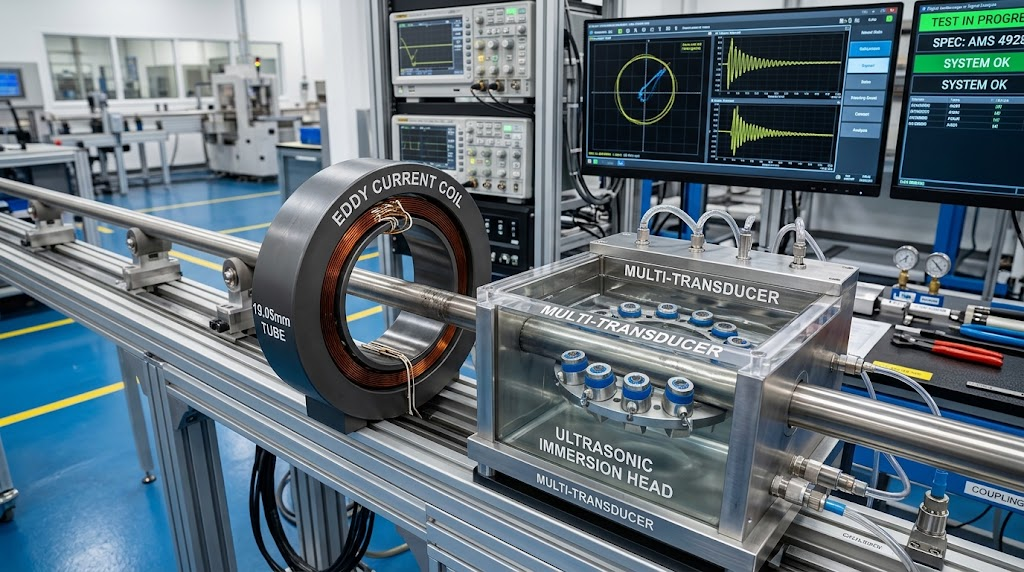
Volumetric Ultrasonic Testing (UT): Performed in accordance with AMS 2631 Class AA (for critical aerospace rotor and rotating shaft stock) or Class A1. Bars are evaluated using computerized multi-transducer immersion tanks to detect internal voids, shrink cavities, micro-porosity, and high-density tungsten or low-density interstitial inclusions down to 0.79 mm (1/64 in.) Flat-Bottom Hole (FBH) calibration equivalency.
Surface Flaw Detection: Rotary or encircling-coil Eddy Current Testing (ET per ASTM E426) continuously inspects 100% of the bar's cylindrical perimeter, identifying longitudinal seams, roller laps, and grinding micro-checks down to a defect depth threshold of 0.05 mm.
Fluorescent Penetrant Inspection (FPI): Finished ends, chamfers, and ground faces are periodically evaluated per AMS 2647 to verify zero localized surface tears or micro-cracks.
Precision straightness achieved through multi-stage grinding is vulnerable during intermodal ocean transit and handling. Long, slender titanium rods flex under their own weight and can suffer permanent plastic deformation if handled improperly by forklifts or subjected to point-loading during transit.
China Titanium Factory prevents shipping-induced damage through an engineered export packaging protocol:
Individual Bar Protection: Ground rods are cleaned of residual swarf and oil, then sleeved in individual extruded low-density polyethylene (LDPE) netting or rigid PVC shrink sleeves to prevent surface-to-surface fretting abrasion. Bars ≤ Ø 12 mm intended for medical bone screw stock are inserted into individual rigid thin-wall plastic tubes.
Multi-Point Internal Cradles: Rod bundles are seated inside heavy wooden bulkheads positioned at intervals of no more than 800 mm, preventing gravitational sag and eliminating dynamic bending moments during forklift movements.
Hermetic Vapor Barriers: Crates are fully lined with heavy-duty Vapor Corrosion Inhibitor (VCI) heat-sealed barrier film, accompanied by desiccant canisters to prevent condensation and salt-spray corrosion during multi-week ocean transit.
Rigid Crating: Master containers are built using solid 20 mm exterior-grade hardwood compliant with ISPM 15 fumigation standards, reinforced with external steel perimeter straps and heavy-duty skids for stable handling.
Technical FAQ: Titanium Rod Straightness, Grinding Tolerances & QA Verification
Is it more cost-effective to buy standard hot-rolled/pickled ASTM B348 titanium rod or pay a premium for centerless ground ISO h7 rod?
For CNC turning lots exceeding 50 pieces or any operation utilizing automatic bar feeders, centerless ground ISO h7/h6 stock yields an overall finished-part cost reduction of 18% to 30%. While raw mill-pickled rod carries a 15% to 22% lower initial material purchase price per kilogram, it forces the machinist to buy raw stock 1.5 mm to 2.0 mm oversize to turn off ovality, runout, and the hard alpha-case layer. This converts expensive titanium into low-value scrap chips. Furthermore, running out-of-straight, scaly bar stock causes guide bushing seizures, accelerates carbide insert breakdown by up to 65%, and requires continuous operator supervision, erasing raw material cost savings.
How can QA engineers verify on an EN 10204 3.1 Mill Test Certificate (MTC) that titanium bars will not warp during asymmetric CNC milling?
QA auditors should review four specific parameters on the certified EN 10204 3.1 document before approving raw material release:
Thermal Delivery Condition: Confirm the thermal cycle explicitly lists “Annealed + Stress-Relieved Post-Straightening” (furnace temperature documented at 540°C–650°C for alpha-beta alloys), rather than merely “Hot-Rolled” or “Cold-Worked.”
Microstructural & Alpha-Case Clearance: Ensure positive confirmation of metallographic etch inspection (AMS 2642) reporting “Zero Alpha-Case Present on Surface.”
Actual Dimensional Runout Log: The MTC must state actual measured maximum TIR camber (mm/m) and multi-point out-of-roundness across that specific heat-treat lot.
Ultrasonic Inspection Stamp: Look for independent laboratory sign-off indicating 100% volumetric UT testing compliant with AMS 2631 Class AA or Class A1.
Why do standard 2-point anvil micrometers fail to detect out-of-roundness on centerless ground titanium rods?
During centerless grinding, improper blade geometry, unbalanced wheel speeds, or misaligned feed angles generate an odd-lobed constant-breadth geometric profile (most commonly a three-lobed Reuleaux triangle). Because the profile has a constant cross-sectional breadth, a conventional two-point hand micrometer measures the exact same diameter reading regardless of how it is rotated around the rod. However, the true radius from the central geometric axis varies continuously. When this lobed rod enters a precision circular bushing or three-jaw chuck, it binds against the peaks. True circularity must be verified by rotating the bar inside a 60° V-block beneath a dial indicator, or via non-contact multi-axis laser metrology.
What are the precise end chamfering dimensions required for high-speed automatic bar feeders?
Standard saw-cut titanium rod ends feature sharp outer-diameter burrs, localized expansion swell, and square edges that damage the elastomeric seals, collets, and guide mechanisms of high-speed bar feeders. For seamless operation, incoming titanium stock should feature a machine-cut 30° chamfer (for Swiss lathes) or 45° chamfer (for standard multi-spindle feeders) extending to a depth of 1.5 mm to 2.5 mm, paired with a faced, deburred leading edge. This ensures smooth entry into the bar-pusher collet, maintains hydrodynamic centering oil flow, and prevents guide-bushing scoring during high-speed feed cycles.
Related Technical Specifications & Material Grade Hub: Consultation & Custom Grinding RFQ
China Titanium Factory delivers fully certified titanium round stock configured to exact straightness and surface roughness requirements. To review our standard product offerings, compare cross-grade chemistry, or evaluate our downstream contract manufacturing capabilities, explore the engineering resources linked below:
| Resource & Material Grade Hub | Core Material Specifications | Primary Engineering Domain |
|---|---|---|
| Precision Ground Titanium Rod | ASTM B348, AMS 4928, ASTM F136 (h6/h7, ≤ 0.25 mm/m) | Precision Swiss CNC screw turning, medical implants, high-RPM shafts. |
| Aerospace & Industrial Titanium Bar Stock | ASTM B348, ASME SB348, AMS 4965, MIL-T-9047 | Heavy-section structural forgings, chemical processing autoclaves, oil & gas OCTG. |
| Titanium Metal Grades (Grade 1-23 ELI) | Grades 1, 2, 4, 5 (Ti6Al4V), 7, 9, 12, 23 (ELI) | Metallurgical selection matrix: corrosion resistance, mechanical strength, transus temps. |
| Precision 5-Axis Titanium CNC Machining | AS9100D / ISO 9001 Turnkey Machined Components | Finished aerospace actuation assemblies, complex bone plates, subsea pump rotors. |
Technical Consultation & Mill Test Certificate (MTC) Requests
Eliminate machining distortion, guide-bushing seizures, and raw stock quality issues. Connect directly with the metallurgical engineering team at China Titanium Factory to establish precise stock allowances, thermal stress-relief schedules, and non-destructive testing protocols for your next production run.
Direct Metallurgical Inquiries: sales@chinatitaniumfactory.com