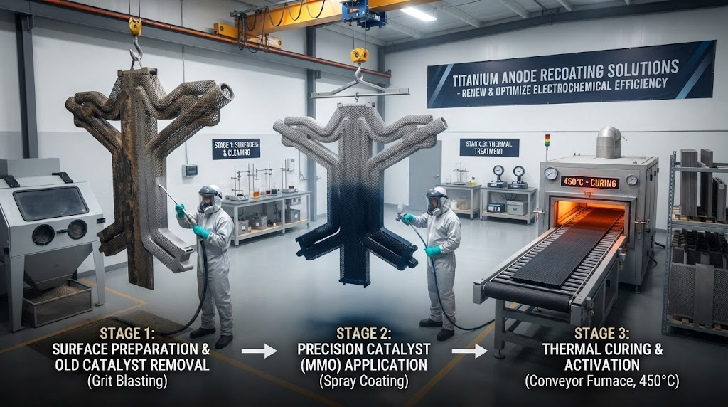
Recoating titanium anodes involves chemically stripping exhausted mixed metal oxide layers from dimensionally stable titanium structures and re-applying catalytic electrocatalysts like Ruthenium(IV) Oxide and Iridium(IV) Oxide via thermal decomposition. This refurbishment workflow restores design cell operating voltages, reduces overpotential by up to 400 mV, and reclaims 100% of the underlying titanium structural asset without paying for new metallurgical fabrication.
In electrochemical production lines, dimensionally stable anodes (DSA) degrade through three distinct physical phenomena. Understanding these mechanisms dictates when an industrial cell must be pulled for recoating before unrecoverable substrate degradation occurs.
During severe polarization in chlor-alkali, copper electrowinning, or cathodic protection systems, active noble metal components slowly dissolve into the electrolyte. Operating at excessive current densities accelerates the consumption of the oxide matrix, causing microscopic fractures and mechanical spalling.
As electrolyte penetrates cracked or depleted catalytic coatings, oxygen species migrate directly to the Grade 1 titanium interface. This generates a non-conductive, stoichiometric titanium dioxide (TiO₂) passivation layer between the substrate and the coating, driving cell resistance exponentially upward.
Engineering Definition: Anode Passivation represents the critical state where interfacial TiO₂ formation prevents electron transfer across the base-metal-to-coating boundary, triggering severe terminal voltage runaways regardless of residual surface catalyst.
Cell Voltage Runaway: Operating voltage increases by >300 mV at steady-state current density.
Declining Current Efficiency: Specific product yield (e.g., metric tons of chlorine or electrowon copper) drops by 5% to 15% per kiloampere-hour.
Localized Thermal Anomalies: Infrared thermography reveals temperature differentials across the anode surface exceeding 12°C, indicating current redistribution.
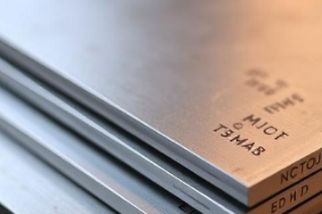
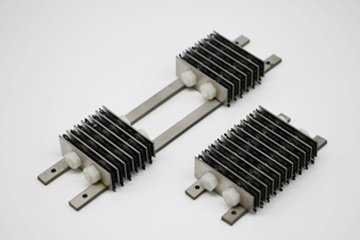
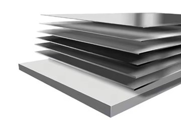
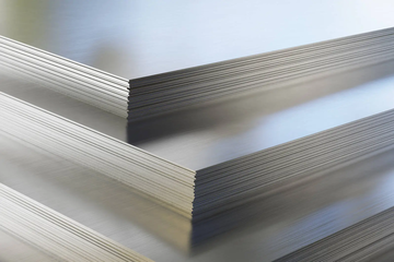
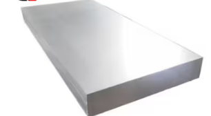
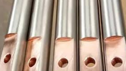
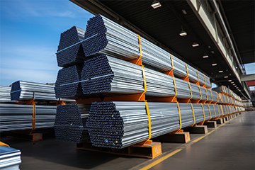
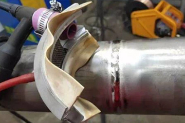
Industrial electrolyzers utilize specialized structural designs made from ASTM Grade 1 and Grade 2 Titanium Sheets, solid current-distribution busbars, and engineered mounting lugs. Purchasing newly fabricated anode structures entails substantial expenses in raw metal procurement, certified precision welding, and CNC machining.
Refurbishing spent structures through recoating eliminates the expense of raw material extraction and metal forming. Because the underlying titanium base metal remains structurally intact after chemical de-coating, plant operators recover up to 50% of the capital expenditure demanded by new anode assemblies.
| Cost Factor / Operational Parameter | New Anode Procurement | Substrate Recoating Service | Industrial Variance (%) |
|---|---|---|---|
| Titanium Substrate Material & Forming | 100% (Base Cost) | 0% (Reused Substrate) | -100% Material Cost |
| Precision CNC Machining & Welding | High (CAD/CAM Setup + Labor) | Minimal (Lug Straightening/Audit) | -80% Labor Outlay |
| Noble Metal Coating (Ru, Ir, Ta, Pt) | 100% Application Cost | 100% Application Cost | Parity (Equal Loading) |
| Overall CAPEX per Square Meter | $1,100 – $1,800 / m² | $550 – $900 / m² | 35% – 50% Net Savings |
| Substrate Service Lifetime Potential | Single Cycle (3–8 Years) | Multiple Cycles (Up to 4-6 Recoats) | +400% Asset Utilization |
When high-volume operators deploy Custom Titanium Fabrications & Assemblies, recoating preserves structural geometries without introducing dimensional assembly variations to the cell room.
In continuous electrowinning and chlor-alkali electrolysis, electrical power represents over 60% of total operating expenses (OPEX). A passivated anode adds severe overpotential penalties, driving up daily megawatt-hour consumption.
The direct relationship between operational cell voltage and electrical energy consumption per unit of electrodeposited or evolved chemical product is defined by Faraday's Law:
W = (Vcell × n × F) / (3600 × M × η)
Where:
• W = Specific energy consumption (kWh / metric ton)
• Vcell = Average operating cell voltage (V)
• n = Valence electron transfer number
• F = Faraday constant (96,485 C/mol)
• M = Molar mass of product (g/mol)
• η = Current efficiency decimal (0.85 – 0.98)
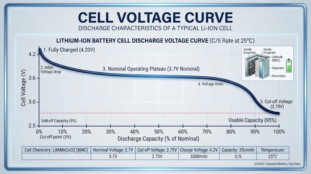
Applying industrial refurbishment strips the high-resistance passivation barrier and reinstates a low-overpotential electrocatalyst, yielding a documented 200 to 400 mV (0.2 V to 0.4 V) drop in overall cell voltage.
For a chlor-alkali circuit operating at 100 kA with 60 membrane cells, an average voltage drop of 300 mV (0.3 V) across all recoated assemblies yields:
Total Instantaneous Power Saved: P = 60 cells × 100,000 A × 0.3 V = 1,800,000 W = 1.80 MW
Annual Electricity Saved (8,400 run hours): 1.80 MW × 8,400 h = 15,120 MWh/year
Direct Cost Reductions (@ $0.075/kWh): 15,120,000 kWh × $0.075 = $1,134,000 Saved Annually
Refurbishing titanium substrates without damaging delicate meshes requires an exact, standardized operational standard. At China Titanium Factory, we utilize our proprietary six-stage procedure to preserve metallurgical integrity and deliver uniform catalytic coating performance.
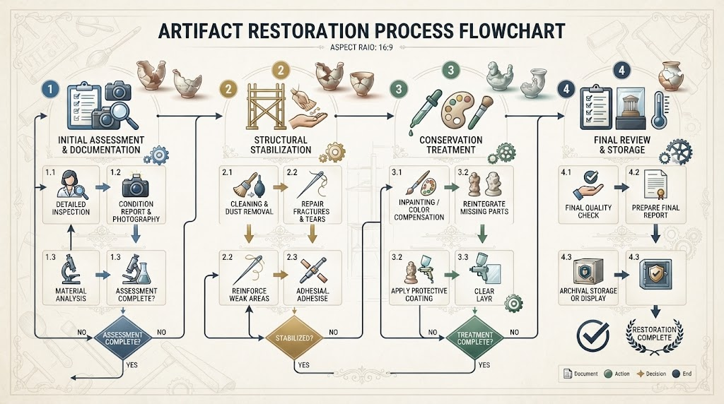
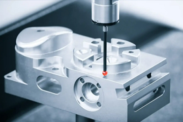
Spent anodes undergo ultrasonic thickness gauging and optical CMM coordinate measurements to verify structural straightness within ±0.5 mm tolerances. Dye-penetrant inspections according to ASTM E1417 standards screen for baseline weld cracks or deep substrate crevices.
The exhausted mixed metal oxide layer is selectively removed in an inhibited chemical stripping matrix. This process digests the depleted ruthenium and iridium oxides while inhibiting chemical attack on the pure titanium base.
The stripped substrate is subjected to hot oxalic acid etching (10–15% at 90°C) to remove passive oxide residues and create an anchor profile. Surface roughness is brought to a controlled Ra 3.5 to 5.0 µm, expanding the interfacial surface area for mechanical interlocking of the new coating.
Noble metal salts (RuCl₃, IrCl₃, H₂PtCl₆, and organometallic Tantalum complexes) are compounded with analytical purity (>99.95%) according to application-specific stoichiometry.
The precursor solution is deposited via automated, robotic precision brushing or micro-spraying in controlled cross-patterns. The anode undergoes cyclic multi-stage baking in industrial convection furnaces at 400°C to 520°C. This sequence is repeated 18 to 26 times to build the specified oxide crystal structure layer by layer.
Every batch undergoes X-Ray Fluorescence (XRF) loading audits across 12 discrete measurement coordinates to guarantee exact noble metal density (g/m²). Accelerated life samples are pulled for electrochemical testing.
Selecting the correct chemical stripping regime protects the underlying titanium substrate from pitting, excessive wall-thinning, and destructive hydrogen embrittlement.
| Stripping Methodology | Base Metal Loss (µm/cycle) | Risk of Hydrogen Embrittlement | Suitability for Thin Expanded Meshes |
|---|---|---|---|
| Inhibited Boiling Acid Leaching (China Titanium Standard) | < 5 µm (Controlled) | Extremely Low (Oxidizing passivator buffers) | Optimal (Maintains structural cross-sections) |
| Molten Nitrate/Hydroxide Salt Bath (450°C) | 10 – 25 µm | Low (High temperature limits hydrides) | Moderate (Risk of thermal warpage on <1.0 mm mesh) |
| Coarse Grit Abrasive Blasting | > 50 µm (Uncontrolled) | Negligible (Mechanical only) | Unacceptable (Blasts through mesh intersections) |
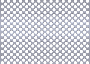
Unbuffered non-oxidizing acid pickling can cause nascent hydrogen to penetrate the interstitial lattice of Titanium Expanded Mesh and Ribbons, forming brittle titanium hydride (TiH₂) phases. We utilize specialized chemical inhibitors during de-coating to maintain residual hydrogen levels below the strict 50 ppm threshold mandated by ASTM standards.
A successful recoating project requires selecting an oxide formulation engineered specifically for your chemical operating environment. Using a chlorine-evolution coating in an oxygen-evolving system will cause catastrophic coating failure within weeks.
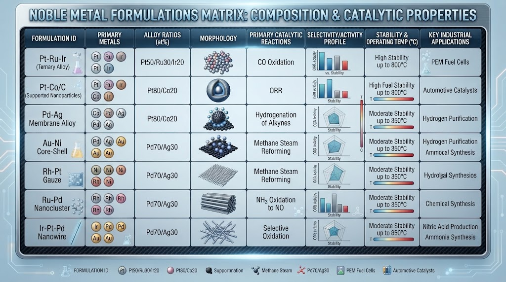
Engineered primarily for chlorine evolution (Cl₂) in chlor-alkali membrane cells, brine electrolysis, and sodium hypochlorite generators. Ruthenium oxide offers exceptional electrocatalytic activity and lowest overpotentials in high-chloride electrolytes, with added iridium stabilizing the crystal lattice against trace oxygen evolution.
The industrial benchmark for oxygen evolution (O₂) in strong acid solutions. Widely deployed across copper and zinc electrowinning, continuous steel electro-galvanizing, printed circuit board (PCB) copper foil manufacturing, and impressed current cathodic protection (ICCP). The tantalum component creates an acid-resistant valve-metal barrier that shields against aggressive sulfuric or nitric acid attacks.
Formulated for electroplating baths (gold, rhodium, hard chrome) and specialized water treatment where pure metallic catalysts are required to prevent organic bath contamination.
| Electrolyte / Industrial Sector | Dominant Anodic Reaction | Recommended Coating Chemistry | Standard Noble Metal Loading |
|---|---|---|---|
| Chlor-Alkali (NaCl / KCl Brine) | 2Cl⁻ → Cl₂ + 2e⁻ | RuO₂ - TiO₂ - IrO₂ | 10 – 25 g/m² (as Ru+Ir) |
| Copper / Zinc Electrowinning | 2H₂O → O₂ + 4H⁺ + 4e⁻ | IrO₂ - Ta₂O₅ | 12 – 40 g/m² (as Ir) |
| Cathodic Protection (Seawater / Soil) | Mixed (Cl₂ & O₂ Evolution) | IrO₂ - Ta₂O₅ - RuO₂ | 6 – 12 g/m² (as Ir+Ru) |
| PCB / Hard Chrome Electroplating | O₂ Evolution / Passivating Acid | Pt (Electroplated) or Ir-Ta | 2.5 – 5.0 µm Pt thickness |
To explore newly fabricated anodes or custom catalytic formulations, review our full catalog of Mixed Metal Oxide (MMO) Titanium Anodes.
Refurbished anodes must perform to the same operational standards as brand-new units. At China Titanium Factory, our quality assurance protocols ensure every recoated batch delivers reliable industrial service.
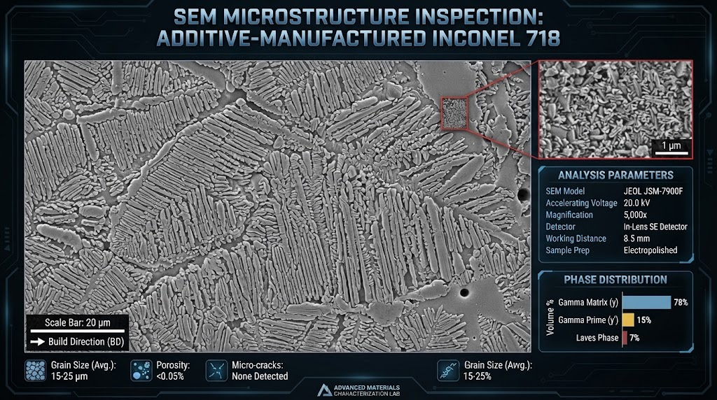
All incoming and de-coated substrates are verified against ASTM B265 (Standard Specification for Titanium and Titanium Alloy Strip, Sheet, and Plate). Grain structure, yield strength (min 170 MPa for Grade 1), and chemical composition are cataloged before thermal processing begins.
Non-destructive XRF spectrometry validates precious metal loading per unit area across multiple grid coordinates on the anode plate. This guarantees exact compliance with the specified noble metal density (e.g., 20.0 ± 0.5 g/m² Ir-Ru content).
Periodic coupon samples undergo destructive life tests following NACE TM0108 test methods. Operating at elevated current densities (10,000 to 20,000 A/m² in 1.0 M H₂SO₄ at 60°C), our coatings reliably exceed the target operational hours before showing an overpotential inflection of 5.0 V.
Not every spent anode can be safely refurbished. When evaluating substrates for recoating, plant engineers should apply the following inspection criteria:
Residual Base Thickness: ≥80% of original nominal drawing specification (ASTM B265).
Localized Pitting Depth: Maximum pitting depth must not exceed 0.25 mm on solid plate or 15% of mesh strand thickness.
Structural Warping / Distortion: Planar camber ≤1.5 mm per linear meter of anode span.
Weld Seam Integrity: Current distributor-to-mesh weld joints must show zero stress-corrosion cracking under liquid penetrant inspection.
To receive a rapid technical quote and turnaround schedule from our engineering desk, prepare the following parameters:
1. Operating Electrolyte Chemistry: Concentrations of chlorides (Cl⁻), sulfates (SO₄²⁻), fluorides (F⁻), organics, and trace metals (Mn, Fe, Co).
2. Operating Parameters: Working current density (A/m² or A/dm²), operating bath temperature range (°C), and target cell voltage limit.
3. Physical Substrate Specs: Overall dimensional CAD drawings, sheet thickness, expanded mesh strand geometries, and mounting lug details.
4. Historical Operating Hours: Total running hours of spent anodes and primary reason for extraction (e.g., scheduled outage vs. sudden voltage surge).
Industrial Grade 1 and Grade 2 titanium substrates can typically be stripped and recoated 4 to 6 times. As long as chemical stripping avoids mechanical abrasion and does not breach minimum structural thickness thresholds, the base titanium metal remains reusable for decades.
The most common causes include presence of trace fluorides (>10 mg/L F⁻) in the electrolyte which dissolves the protective titanium base metal, severe reverse polarization currents, organic surface fouling, and incorrect noble metal formulation for the dominant gas evolution reaction.
Standard batch recoating turnaround times range from 10 to 20 working days upon receipt of substrates at our facility, depending on batch volume, geometry complexity, and required thermal baking layers.
Yes. Our automated stripping baths and multi-axis thermal decomposition application systems accommodate expanded mesh baskets, slotted plates, tubular probes, concentric cylinders, and large welded industrial busbar assemblies.
Send us your spent anode drawings, operating parameters, and batch quantities. Our metallurgical engineering team will provide a rapid assessment, stripping review, and recoating quotation tailored to your operational environment.
Request a Recoating Technical Evaluation


Contact Us
Room 21003, 10th Floor, Unit 2, Building 1, Xianning International Plaza, No.29 Xianning West Road, Beilin District, Xi'an City
Copyright © Xi'an Shiguang Jingyan Technology Co., Ltd. All Rights Reserved.